Where the μm Step Disappears: Measuring Both-Side Thickness Simultaneously with a Two-Channel Chromatic Confocal Controller
If a coating layer on a lens assembly line comes out 2 µm thinner than its design value, an ordinary 2D vision camera cannot see this deviation at all. Neither color nor shape changes — only the ‘distance’ between the surface and the boundary beneath it shifts, and only slightly. A single-camera imaging approach is, from the outset, asking for information along an axis (displacement along the optical axis) that it was never built to measure.
Leaving this axis unaddressed lets coating non-uniformity or over/under-applied adhesive layers flow straight into the next process. For an optical component, this surfaces later as focus shift or chromatic aberration; for an injection-molded lens housing, it surfaces as an assembly defect — both discovered late, at a far higher rework cost. The solution is not ‘area’ imaging with a camera, but a Chromatic Confocal sensor that uses the difference in focal distance by wavelength to achieve sub-µm precision at the level of a single ‘point.’ Recently, product lines that pair this sensor in two channels to measure both sides (top and bottom) of a transparent sample simultaneously with a single controller have emerged, and a clear trend is pushing thickness inspection itself up to line speed.
Why chromatic confocal is said to measure distance with a spectrometer, not a camera
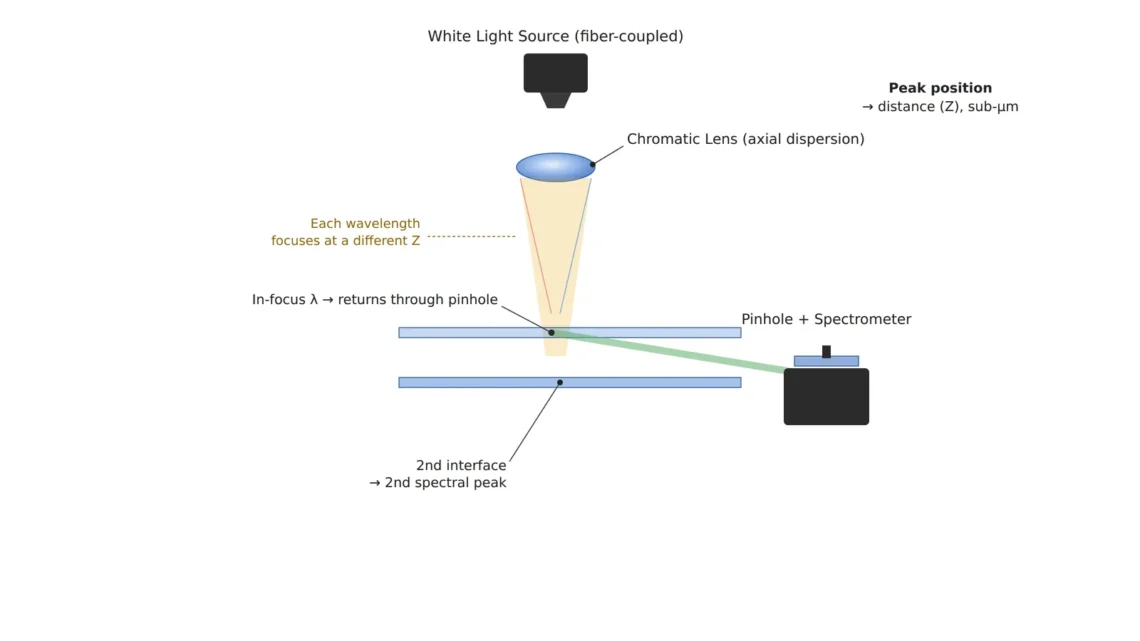
Instead of capturing the ‘brightness distribution’ of reflected light as an image the way an ordinary camera does, a chromatic confocal sensor uses an optical system whose axial chromatic aberration has been deliberately maximized. When white light passes through this lens, the distance at which each wavelength comes to focus differs minutely, and only the light at the wavelength that focuses exactly on the target surface passes back through the pinhole to the spectrometer[3][4]. In other words, what a chromatic confocal sensor actually measures is ‘which wavelength came back,’ and it converts this spectral peak position through a lookup table to calculate the distance to the target (the Z value) at sub-micron precision.
This principle gives a unique advantage in thickness measurement. For a transparent or semi-transparent material, reflection occurs once at the surface and again at the boundary beneath it, producing two peaks in the spectrum; recent controllers can detect and separate these multiple peaks simultaneously, calculating thickness for up to five layers from a single head[3]. In contrast to camera-based 2D vision, which excels at finding changes in color and shape, chromatic confocal is a fundamentally different tool in that it converts an inherently ‘invisible’ displacement along the optical axis directly into a spectral signal.
Why the two-channel controller emerged: both-side thickness at once
Previously, measuring the top and bottom thickness of a sample simultaneously typically meant connecting two heads to two separate controllers and subtracting the two values after synchronizing them in software. This configuration had a weakness: timing error between the two controllers accumulated directly as thickness error. Recently released two-channel controllers connect two heads to a single controller and process the inter-channel computation directly inside the controller, with the compact type disclosed at up to 8 kHz and the high-performance type at up to 25 kHz measurement speed, both at sub-micron (2 nm class) resolution[1][2].
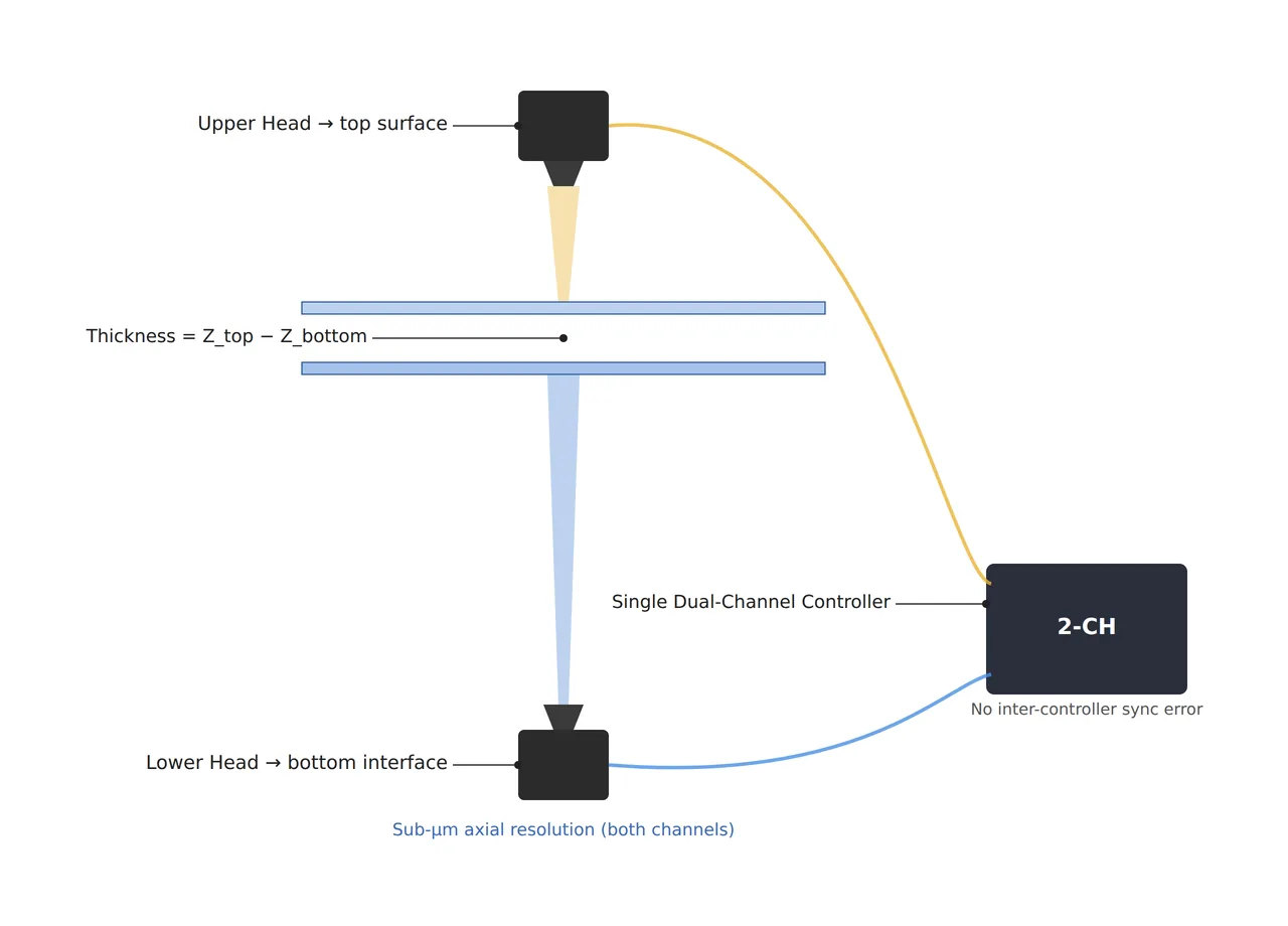
Assuming the target is a general manufacturing context rather than a secondary-battery-related process, this two-channel, multi-peak configuration proves its worth in practice for parts where ‘the distance between the top and bottom surfaces’ is itself the quality indicator — thickness deviation in an injection-molded lens dome, the thickness of solder resist or a coating layer applied on a PCB, or the both-side flatness of a glass cover. Measuring both sides at once with a single controller structurally eliminates head-to-head synchronization error, and inspection cycle time drops by nearly half compared with sequential measurement.
The trade-off among lens specification, WD, and algorithm parameters
The first value to check when selecting a chromatic confocal head is the measuring range and the optical WD (working distance) tied to it. A narrower measuring range yields sub-micron-class resolution, but it also shortens the clearance between the head and the target surface, making the setup more vulnerable to vibration or conveyor wobble. A recently disclosed head for high-temperature, vacuum environments uses a stainless-steel construction with no organic adhesive to withstand up to 200 °C, but this too is a trade-off within a lineup of short-WD heads with a measuring range of roughly 0.8–4 mm[2][5].
On the algorithm-parameter side, filtering by spectral peak reliability is the key. If the target surface’s reflectivity is too low or diffuse scattering is severe, the spectral peak itself can smear and be misdetected as noise, so the controller must set a peak-intensity threshold together with a limit on the number of multiple peaks. As with the specular/diffuse reflection problem discussed earlier, this means that no matter how good a head’s specifications are, it will not produce a stable value unless the target’s surface material and reflectivity are checked first.
Core framework matching table
| Item | Spec |
|---|---|
| ① Minimum detectable step / thickness deviation | Sub-micron (roughly within 2 µm; requires confirmation — to be fixed by sample testing per head measuring range and material) |
| ② Optical setup — illumination | Dedicated chromatic-confocal white light source (halogen or white LED), fiber-optic coupling |
| ② Optical setup — lens/head | For heads in the 0.8–4 mm measuring-range class, WD requires confirmation (varies by head model); for a two-channel configuration, secure alignment clearance for both heads |
| ③ Algorithm parameters | Measurement speed up to 8–25 kHz, multi-peak separation (up to 5 layers), peak-reliability threshold filtering |
As the table shows, chromatic confocal carries a structural trade-off: the higher the resolution, the less clearance remains for WD and vibration tolerance. On a line with significant vibration, it is safer to select a head by securing measuring range first, ahead of resolution.
When structured-light 3D is favorable, and when chromatic confocal is favorable
Even when both deal in µm-scale measurement, the structured-light moiré 3D inspection covered previously excels at reconstructing the entire shape (areal data) of a sample surface’s whole surface in one pass, while chromatic confocal excels at repeatedly measuring distance/thickness at a specific point (or points) with far higher axial resolution. If you need to see the full 3D profile of an entire solder bump, structured light is the more reasonable choice; if you need to repeatedly track the thickness deviation of a specific coating layer at conveyor-line speed, chromatic confocal is closer to the reasonable choice.
However, if the target is a multilayer transparent material where the reflectivity difference between layers is not large, the spectral peaks can overlap and make layer separation itself difficult. Whether chromatic confocal actually delivers stable multi-peak separation in such a combination cannot be confirmed before sample testing.
Field Checkpoints
- Is the head-to-target WD physically achievable even accounting for vibration and conveyor wobble?
- Has the target’s surface material and reflectivity been measured to set the peak-reliability threshold in advance?
- In a two-channel configuration, is the optical-axis alignment error between the top and bottom heads within the tolerance for thickness-calculation error?
- For a multilayer transparent sample, has cross-validation with samples confirmed that the inter-layer spectral peaks actually separate?
References and Patents
- [1] Micro-Epsilon, “Next-gen: high-performance confocal chromatic controllers” (IFC2412/IFC2417 two-channel controller disclosure materials), micro-epsilon.com
- [2] Instrumentation Monthly, “New compact two-channel confocal controllers enable two-sided thickness measurements using just one controller”, instrumentation.co.uk
- [3] US20230417533A1, “Chromatic confocal measuring device” — Assignee: Precitec Optronik GmbH (Google Patents)
- [4] US10197382B2, “Chromatic confocal sensor” — Assignee: Mitutoyo Corporation (Google Patents)
- [5] US9541376B2, “Chromatic confocal sensor and measurement method” — Assignee: Mitutoyo Corporation (Google Patents)
- [6] US6657216B1, “Dual spot confocal displacement sensor” — Assignee: Onto Innovation Inc. (formerly Nanometrics Incorporated) (Google Patents)


You May Also Like
Specular Reflection Erases Defects: How Cross-Polarization Catches Missed Detections on Highly Reflective Surfaces
Parts at Every Height, One Focus Plane — Can It All Stay Sharp? Liquid-Lens EDOF and the Division of Labor with Interface Bandwidth