Catching 20 μm Sink Marks in High-Gloss Injection-Molded Parts with Phase Measuring Deflectometry (PMD) — The Last Gap Polarization Fusion Fills
OPTICS · ALGORITHM
The most common report on a high-gloss injection-molded inspection line is “the eye can see it, but the camera can’t catch it.” Shallow sink marks, orange peel, and micro-scratches on a painted or piano-black injection surface are only 20–50 µm deep, and because the surface itself behaves like a mirror, almost no contrast forms no matter how evenly you lay down diffuse illumination.
Leaving this condition unaddressed shifts the cost downstream, out of the inspection process. If it is caught at final appearance inspection after painting, the paint cost has already been sunk; if it is caught in the field after shipment, an appearance claim leads to a full recall. This is a textbook case where the unit cost of a single missed defect outweighs the inspection equipment investment.
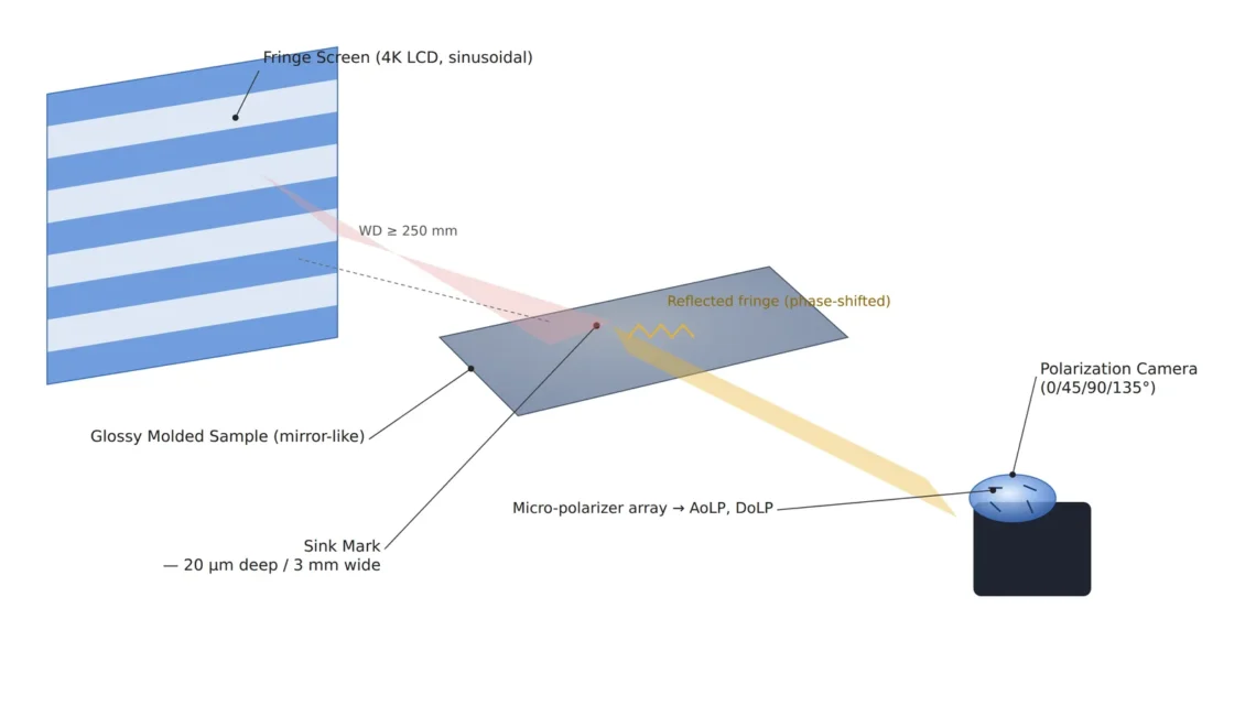
The solution is not brighter lighting — it is using the specular reflection itself as the signal. Phase Measuring Deflectometry (PMD) treats the target surface as a “mirror” between the camera and a screen: it reads, in units of phase, how much a sinusoidal fringe pattern displayed on the screen distorts as it reflects off the surface, and reconstructs the surface’s slope field from that distortion.
In specular-surface inspection, diffuse reflection is the enemy, but specular reflection is not the enemy — it is a signal not yet decoded.
PMD does not measure height — it measures slope
Point. The reason Phase Measuring Deflectometry achieves resolution that overwhelms structured light is that it measures a different quantity.
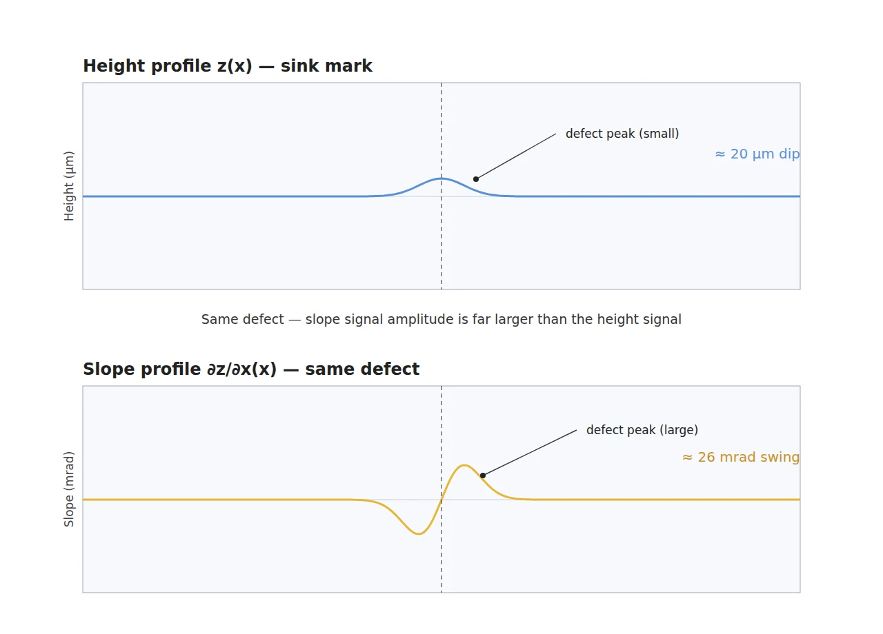
Reason. Structured light triangulates surface height z directly. PMD, in contrast, first obtains the slope of the surface normal and integrates it to recover shape. Because slope is the derivative of height, under the same optical conditions a slope measurement is far more sensitive to shallow defects than a height measurement. A sink mark 3 mm wide and 20 µm deep is only a 20 µm change in height, but it becomes a clear signal of several milliradians (mrad) when expressed as a slope change.
Example. Assume an ABS piano-black injection-molded cover (reflectivity requires empirical measurement; the specular component typically dominates) with a shallow depression 3 mm wide and 20 µm deep. The resulting slope amplitude is roughly 26 mrad. At a screen-to-target distance of 400 mm, this is magnified into a fringe displacement of about 20 mm on the screen plane. In other words, a µm-scale defect is amplified into a mm-scale phase displacement.
Point. That is why, on a specular surface, switching the measured quantity to slope comes before reaching for “a better 3D sensor.”
The integration-constant problem — a structural limit of PMD alone
Point. The structure of integrating slope to obtain height comes with a cost: ambiguity in absolute height and surface normal.
Reason. All the camera observes is which screen pixel arrived at which camera pixel. A single observation cannot simultaneously determine both the 3D position of a point on the surface and that point’s normal. For this reason, conventional PMD has always required one of the following: a second camera, screen movement, or a prior assumption about shape.
Example. Commercial deflectometry sensors in practice resolve this ambiguity with a two-camera configuration. The related patent families also separately specify a calibration reference plate (a reflective surface bearing a predefined pattern with markings), because the geometry of the screen, camera, and target itself is the dominant factor in measurement uncertainty.
Point. When reviewing PMD adoption, “can this be done with one camera?” is not the right question to ask — it should be reframed as what means is used to resolve the ambiguity.
The 2026 shift — fusion that uses polarization as a slope prior
Point. Recent research trends draw the missing constraint not from a second camera but from polarization (Shape from Polarization, SfP).
Reason. On a specular surface, the polarization state of reflected light depends decisively on the angle of incidence, and therefore on the zenith angle of the surface normal. A polarization camera (a sensor with micro-polarizers arranged at 0°/45°/90°/135°) obtains the angle of linear polarization (AoLP) and degree of linear polarization (DoLP) in a single exposure, providing a prior on the normal at every pixel. The phase information from Phase Measuring Deflectometry strongly constrains the azimuth angle, while polarization constrains the zenith angle. Because the two pieces of information are mutually orthogonal constraints, the fusion gain is large.
Example. Polarization-based specular-surface 3D imaging studies published in 2026 combine physics-informed active polarization measurement with deflectometry information, pointing toward improved normal-estimation stability on discontinuous freeform specular objects compared with PMD alone. Separate research over the same period on PMD robustness for automotive paint surfaces shows that large-area freeform surfaces are the main battleground for this technology.
Point. That said, the polarization signal collapses sharply in DoLP depending on surface material, coating, and contamination, so this cannot be confirmed before sample testing.
Polarization fusion is not a technology for removing one camera — it is a technology for adding one constraint. Confusing the two collapses the setup.
Core framework — minimum defect size / optical setup / algorithm matching table
| Category | Item | Spec / Parameter | Basis · Notes |
|---|---|---|---|
| ① Min. defect size | Shallow depression (sink mark) | Depth 20 µm / width 3 mm | Converts to a slope amplitude of roughly 26 mrad |
| ① Min. defect size | Micro-scratch | Width 50 µm / depth 5 µm | Detected via slope discontinuity; depth quantification requires separate verification |
| ② Optical setup | Pattern screen | 4K LCD, pixel pitch 0.18 mm, screen-to-target 400 mm | At 26 mrad slope, screen displacement is roughly 20 mm |
| ② Optical setup | Camera | Polarization camera, 2/3-inch, 5 MP (0/45/90/135° micro-polarizers) | Single-exposure acquisition of AoLP and DoLP |
| ② Optical setup | Lens | Focal length 25 mm, F/5.6, FOV 200 mm x 150 mm | Prioritize depth of field; avoid opening the aperture excessively |
| ② Optical setup | WD (Working Distance) | Minimum 250 mm required | Confirm empirically that it does not interfere with the screen structure or shielding |
| ② Optical setup | Illuminance | Operate based on screen luminance; ambient stray light ≤50 lx | Stray light entering the specular path collapses the phase SNR |
| ③ Algorithm | Phase shifting | 4-step, two fringe periods (coarse/fine) | Resolves phase-unwrapping ambiguity |
| ③ Algorithm | Slope threshold | Local slope residual exceeding 5 mrad | Judged from the residual after removing the curvature component |
| ③ Algorithm | Polarization gating | Pixels with DoLP below 0.15 get fusion weight 0 | Automatically excludes regions where the polarization signal has collapsed |
| ③ Algorithm | Minimum defect area | Connected component ≥30 px | Removes single-frame noise |
Table takeaway. The cell in this matching table that fails most often is not ③ but the WD in ②. Because deflectometry ties the screen, target, and camera into a single optical path, physical interference immediately makes measurement impossible, and no amount of algorithm-parameter tuning recovers it.
Related Patents (Confirmed to Exist)
| Patent No. | Title | Assignee |
|---|---|---|
| US 11,092,432 B2 | Reference plate and method for calibrating and/or checking a deflectometry sensor system | Micro-Epsilon Messtechnik GmbH & Co. KG |
| US 10,731,972 B2 | Instantaneous phase mapping deflectometry | Arizona Board of Regents on behalf of the University of Arizona |
| US 10,228,331 B2 | Methods and apparatus for polarized wafer inspection | KLA-Tencor Corporation |
Patents whose assignee could not be explicitly confirmed were excluded from citation.
Conditions Favoring the Opposite Approach
- When the surface is diffuse-reflection dominant (matte paint, textured molding): PMD cannot form a fringe reflection image, so structured light or photometric stereo is favorable.
- When the required measurand is absolute height rather than slope: accumulated integration error becomes a problem, so confocal or interferometric methods are favorable.
- When the target is semi-transparent: surface reflection mixes with internal scattering and contaminates the phase. This requires separate review.
All of the above judgments depend on the physical reflectance profile of the actual part, so this cannot be confirmed before sample testing.
Field Checkpoints
- Is a WD of 250 mm or more confirmed by measurement? — Confirm physical clearance from the screen frame, light shield, and transport jig by measurement, not from drawings.
- Has the ratio of specular to diffuse components on the target surface been measured first? — If the area where DoLP collapses below 0.15 exceeds 30%, the polarization-fusion gain disappears.
- Is ambient stray light shielded to 50 lx or below? — If ceiling-light reflections enter the screen path, phase SNR collapses first.
- Is the means of resolving ambiguity (second camera / screen movement / polarization prior) specified in the equipment spec sheet?
- Is a handling policy (masking or interpolation) defined for pixels where phase unwrapping fails?


You May Also Like
Specular Reflection Erases Defects: How Cross-Polarization Catches Missed Detections on Highly Reflective Surfaces
Where the μm Step Disappears: Measuring Both-Side Thickness Simultaneously with a Two-Channel Chromatic Confocal Controller