Can One Focus Plane Keep Parts of Every Height Sharp?
OPTICS
Stop down to f/16 to fit a connector whose pin heights vary by up to 0.5 mm into one frame, and the 0.61 mm depth of field covers it, but the MTF for a 20 μm crack drops to 0.24, below the 0.31 requirement.
At a 27 mm field with 4,096 px, I calculated depth of field and diffraction MTF for each aperture together, then followed how many frames a liquid lens has to take and whether that data fits within the interface bandwidth.
About 10 min read
The target is a multi-pin connector plated with tin or gold. The pins are metal surfaces with very strong specular reflection, and even within one housing the pin insertion depth varies by 0.3 to 0.5 mm. The defects to find are 20 μm micro-cracks and burrs at the pin tips. Gloss differs from one plating lot to the next and the highlight positions move with it, so the reflectance spread between lots has to be measured before the setup is designed.
Capture the whole part with one fixed-focus lens and the front pin tips come out sharp while the rear pin tips blur. Where the image blurs, the crack boundary itself disappears and becomes a missed detection, and that defect comes back as a contact failure at final assembly. Stop the aperture down to widen the depth and this time diffraction trims the contrast and buries the crack, so the aperture alone leaves a narrow way out.
I solve this problem with two calculations on a single F-number. I check whether the depth of field that covers 0.5 mm and the MTF that keeps a 20 μm crack alive hold at the same F-number, and if they do not, I move on to extended depth of field (EDOF)2, taking several frames while a liquid lens1 shifts the focal plane. After that, the data that grows with the number of frames goes onto the interface.
One frame needs f/16, where the MTF is 0.24
First, the frame of numbers. By my rule of putting a 20 μm crack on three pixels, one pixel has to be 6.67 μm or less, and a camera 4,096 px wide looking at a 27 mm field gives 6.59 μm per pixel, where the crack spans 3.03 pixels. With 3.45 μm pixels the magnification is 0.523, and a 30 mm lens puts the pins about 87 mm from the lens center.
With one 3.45 μm pixel as the allowed blur, depth of field3 is 0.31 mm at f/8 and 0.42 mm at f/11, and covering 0.5 mm in one frame requires an F-number of 13 or more, which means f/16 (0.61 mm) on a real aperture scale. The obstacle is diffraction. The spatial frequency of the crack on the sensor is 47.8 lp/mm, and calculated with the effective F-number that includes magnification, the diffraction-limited MTF4 at f/16 is 0.24.
0.24MTF
Diffraction-limited MTF at f/16 for the 47.8 lp/mm sensor-side frequency of a 20 μm crack
0.31MTF
Minimum MTF the lens must deliver to clear the ΔGV 12 judgment line
13F-number
Minimum F-number needed to cover 0.5 mm of depth of field in one frame
Overlay the judgment line and the conclusion follows. Assuming an intrinsic crack contrast of ΔGV 40 and a 3σ judgment line of ΔGV 12, the system MTF has to be 0.30 or more, and since the pixel aperture takes 0.956 of it, 0.31 is left for the lens. Even an ideal lens without aberrations reaches only 0.24 at f/16. No single aperture keeps both depth and contrast. For a lot whose spread stays within 0.3 mm, one frame at f/8 with its 0.31 mm covers it, so measuring the actual spread comes first.
Open the aperture and buy depth with frames
An electrowetting liquid lens bends the boundary between two liquids with voltage to change its refractive power, so it can shift the focal plane in milliseconds without mechanical motion. The aperture stays open to protect MTF. The missing depth is made up by the number of frames taken at separate focal planes. With the depths of neighboring focal planes overlapping by 20 %, covering 0.5 mm takes 2 frames at f/8, 3 at f/5.6, 4 at f/4 and 6 at f/2.8.
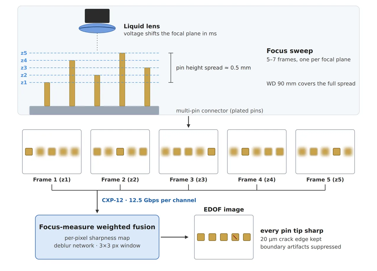
The figure splits a pin-height spread of about 0.5 mm into five focal planes, z1 to z5, and builds one frame with every pin tip in focus through sharpness-weighted fusion5. Each frame is drawn with only one pin sharp, and the depth that matches a 0.125 mm plane spacing is around f/2.8. Taking just two frames at f/8 leaves about three pins sharp in each frame and cuts the frame count by more than half.
There are reasons to open the aperture too. At f/2.8 the lens gathers (8 ÷ 2.8)² = 8.2 times the light of f/8, so exposure can shrink by that much, and on a setup where a fast line raises blur concerns or the coaxial light runs short, the cost of more frames is worth paying. With time to spare, two frames at f/8 give an MTF of 0.60 with the least data, so in my case I would start there. At f/2.8 the focal planes tighten to 0.086 mm apart, so the spec sheet also has to show that the focus repeatability of the liquid lens is comfortably finer than that spacing.
Data and time that grow with the frame count
One 4,096 × 3,000 px frame in 8 bits is 12.3 MB, so assuming the focus sweep finishes within 100 ms, three frames take 369 MB per second, five take 614 MB and seven take 860 MB. By the A3 glossary, one CXP-12 cable of CoaXPress6 carries 12.5 Gbps, or 1.25 GB/s, so three frames use 29 % and even seven frames use 69 %, fitting in one channel. Putting the same seven frames on 1 GigE would need nearly seven times its 125 MB/s theoretical ceiling. That does not work. Seven frames also make 86 MB per part, so the space to hold them in the frame grabber buffer and PC memory until fusion finishes gets calculated in the same table.
Time gets counted too. Assuming a settling time7 of 10 ms for the refractive power to settle after a focus change and an exposure of 0.5 ms, a three-frame sweep takes 31.5 ms, five frames take 52.5 ms and seven take 73.5 ms. Settling time differs with every liquid lens and driver spec sheet, so I replace this cell with the spec sheet value and compare it with the tact budget. On a line where the part moves during the sweep, its position changes from frame to frame, so the conveying conditions need a separate review.
Fusion has a trap of its own. A method that measures per-pixel sharpness in each frame and picks the sharpest can, at the boundary where focus changes, alternate between two frames of similar sharpness and leave stripes that look like defects. The 3×3 px window in the figure is the unit that measures this sharpness, and if the window grows larger than the three-pixel crack width, the crack boundary can mix with blurred pixels from a neighboring frame. In my case, I would keep the window no wider than the crack and check the boundary artifacts on a sample set before putting it on the line.
Setup and judgment conditions for connector pin inspection
Three configurations with different apertures and frame counts go side by side on the same crack. The camera and lens are the same; the only difference is whether depth of field is bought with the aperture or with frames.
| Configuration | ① Minimum defect size | ② Optics · lighting · WD | ③ Algorithm parameters |
|---|---|---|---|
| Fixed focus, one frame, f/16 | Crack 20 μm = 3.03 px (6.59 μm/px) | 4,096 px, 3.45 μm pixels, 30 mm lens at 0.523 magnification, about 87 mm from the lens center (confirm the WD against the spec reference plane), coaxial and diffuse dome lighting, depth of field 0.61 mm | Diffraction MTF 0.24, short of the 0.31 requirement. Not used for crack judgment |
| Liquid lens, two frames, f/8 | Same | Same camera and lens, two focal planes (0.31 mm depth, 20 % overlap), sweep about 21 ms (10 ms settling assumed), 24.6 MB within 100 ms | Sharpness-weighted fusion, sharpness window 3×3 px or smaller, diffraction MTF 0.60, crack candidates at ΔGV 12 or more |
| Liquid lens, four to six frames, f/4 to f/2.8 | Same | Four to six focal planes, 4 to 8.2 times the light of f/8, sweep 42 to 63 ms, 49.2 to 73.7 MB within 100 ms (39 to 59 % of CXP-12) | Diffraction MTF 0.80 to 0.86; the more frames, the longer the boundary-artifact verification |
The three rows together make clear that the choice between buying depth with the aperture or with frames moves MTF and data volume in opposite directions. Holding to one frame gives the least data, but diffraction erases the crack. Adding frames keeps the contrast alive. Sweep time and bandwidth grow along with them. Conversely, for parts whose pin-height spread stays within 0.3 mm, one fixed-focus frame at f/8 is enough, and the liquid lens and fusion only add cost. Plated pins flash their highlights in different places at each focal plane, so whether the fusion result stays the same from lot to lot cannot be guaranteed before a sample test.
Spread measurements and a bandwidth budget in one table
For parts with height spread, a setup estimate goes faster when it starts from one table with a line each for aperture, frame count, sweep time and bandwidth. That table prevents the redesign that comes from choosing the liquid lens and the interface separately, and it also shows the budget owner which item eats the tact time. This article explains technology and is not investment advice. See our Disclaimer.
Field Note
If the pin insertion depth varies by 0.5 mm within one connector housing, I measure the height of each pin with a height gauge or a focus sweep and write down the actual width of the spread. I divide that width by the depth of field of the current aperture to get the number of frames, and add a line each for frames × 12.3 MB and the sweep time to the same table. The settling time of the liquid lens goes in from the spec sheet, and at the first commissioning I check it again by how many frames come out blurred right after a focus change.
Field Checkpoints
With per-pin heights, the frame count and the sweep time written down, run one last check with the questions below before ordering.
- Is the roughly 87 mm from the lens center to the pins (30 mm lens) still secured with the liquid lens module and the coaxial and dome lighting in place? (Confirm the WD again against the spec reference plane.)
- Has the pin-height spread been measured, and was the number of focal planes covering it calculated from the depth of field? (Two frames for 0.5 mm at f/8)
- Does the diffraction MTF at the crack frequency exceed the 0.31 requirement at the intended F-number? (0.24 at f/16 falls short)
- With the settling time of the liquid lens taken from its spec sheet, does the sweep fit within the tact time?
- Does the data rate, frames × 12.3 MB divided by the sweep time, fit within the interface bandwidth? (1.25 GB/s for one CXP-12 channel)
- Is the sharpness window smaller than the crack width, and were fusion boundary artifacts checked on a sample set?
- Is there a plan to measure the reflectance spread of each plating lot and tune the fusion parameters to each lot?
Frequently Asked Questions
Why not set the aperture to f/11 and take just one frame?
The depth of field at f/11 is 0.42 mm, so one frame cannot cover the full 0.5 mm spread. Its diffraction MTF of 0.46 clears the requirement, though, so for lots whose spread stays within 0.42 mm, one frame at f/11 is a candidate. What sets the frame count in the end is the measured spread.
Does switching to a telecentric lens solve the depth problem?
A telecentric lens keeps magnification nearly constant with height, but its depth of field is bound by the same diffraction and F-number limits. At the same magnification and F-number the depth is about the same, so a height spread beyond the depth has to be handled with frames or the F-number.
Glossary
- [1] Liquid lens liquid lens
A lens that shifts focus by changing the curvature of a liquid boundary with voltage. With no mechanical drive, focus changes are fast. ↩ - [2] Extended depth of field extended depth of field, EDOF
A method that merges several frames taken at different focal planes so that a depth range one frame cannot hold comes out sharp throughout. ↩ - [3] Depth of field depth of field
The distance before and behind the focused plane within which the image stays inside the allowed blur. Stopping down deepens it and increases diffraction. ↩ - [4] MTF modulation transfer function
A value showing how much contrast a lens or system keeps at each spatial frequency. The diffraction-limited MTF is the ceiling for a lens without aberrations. ↩ - [5] Sharpness-weighted fusion focus-measure weighted fusion
A method that measures the sharpness around each pixel in every frame and merges them into one, giving more weight to the sharper frame. ↩ - [6] CoaXPress CoaXPress, CXP
A camera interface standard that carries images, power and control signals together over coaxial cable. CXP-12 carries 12.5 Gbps per cable. ↩ - [7] Settling time settling time
The time from a focus command until the refractive power of the lens settles at its target value. ↩
References
- A3, What is CoaXPress? (A3 Glossary): CXP-12 carries 12.5 Gbps (1.25 GB/s) per cable Read the entry
- Diffraction-limited MTF: optical transfer function of a circular aperture, MTF(ν) = (2/π)(φ − cos φ sin φ), φ = arccos(ν ÷ νc), νc = 1 ÷ (λ × N × (1 + m)). J. W. Goodman, Introduction to Fourier Optics, 3rd ed., Roberts & Company, 2005
- Formulas: pixel resolution = field ÷ pixel count; depth of field ≈ 2 × N × c × (1 + m) ÷ m² (c = one pixel); frame count = ⌈(spread − depth) ÷ (0.8 × depth)⌉ + 1; sensor-side frequency = 1 ÷ (2 × defect width) ÷ magnification; pixel aperture MTF = |sin(πνp) ÷ (πνp)|; data rate = frames × frame size ÷ sweep time; thin lens u = f × (1 + 1/m)
- Assumed values: a sensor with 3.45 μm pixels, a 30 mm lens, a 550 nm wavelength, an intrinsic crack contrast of ΔGV 40 with a ΔGV 12 judgment line, 20 % depth overlap between focal planes, 10 ms settling, 0.5 ms exposure and a 100 ms sweep are assumptions for the worked example
Related reading — How Liquid Lens Autofocus Solves Focus on High-Mix, Low-Volume Lines · When Height Varies, F7.1 Beats F16 on a Telecentric Lens · Camera Interface Bandwidth Determines Resolution

Noctvision
An engineer who has handled mechanical design and project management for production equipment since 2005. Here I work through the cameras, lenses and lighting that go into equipment with formulas and public data, and record the assumptions and sources alongside the numbers.


You May Also Like
Why a Line-Scan Camera Chosen by Line Rate Alone Misses Defects
A Mono Camera Catches PCB Color Differences When You Choose the Wavelength