Camera Interface Bandwidth Determines Resolution — From GigE Vision to CoaXPress 2.0
Once you hang six 12MP cameras side by side on a multilayer PCB inspection line, the problem that hits you immediately is not the lens or the lighting — it’s the cable. The moment the raw image data a single camera pours out per second exceeds the limit of a 1GigE link (roughly 115MB/s), the system is forced to choose one of three things: lower the frame rate, lower the resolution, or send only a cropped region of interest (ROI). If this choice isn’t recognized at the design stage and the line is set up anyway, you end up hitting your inspection speed target while a 15 µm-class via-hole crack never even forms on the camera sensor in the first place, for lack of pixel resolution.
Left unaddressed, this bottleneck grows cost in two directions. Either the line can’t keep pace and tact time slips, or the frame rate is forced to match by cutting resolution and bit depth, letting fine cracks slip through as missed defects. The latter, if it surfaces as a field failure after assembly, comes back at tens of times the cost of redesigning the inspection system. There are two branches of solution: physically increasing the interface bandwidth itself (adopting CoaXPress 2.0), or algorithmically reducing the transmitted volume by selecting only the region of interest at the edge. This article maps how these two solutions actually connect to detection performance (resolution and frame rate) in a matching table.
Why bandwidth becomes the bottleneck for resolution
Point. A camera interface’s effective bandwidth is, in effect, the ceiling that determines “how many pixels can be inspected per second.”
Reason. Whether line-scan or area-scan, no matter how sophisticated the inspection algorithm is, if the raw image cannot be delivered in real time from the camera sensor to the host PC (or edge computing unit), that frame was never a candidate for analysis in the first place. When the product of resolution (MP) and frame rate (fps) exceeds the interface bandwidth, the system switches into frame-drop or bandwidth-limited mode, and this switch usually cuts detection resolution rather than line speed.
Example. Driving a 12MP (4096×3000, 8-bit mono) camera at 60 fps requires transmitting roughly 2.2 GB per second. A single 1GigE link (roughly 115MB/s) isn’t remotely enough, and even bonding multiple 5GigE links (roughly 575MB/s) still falls short. A single CoaXPress 2.0 cable, by contrast, supports 12.5 Gbps (roughly 1.56 GB/s), leaving room to cover the same 12MP/60fps condition on a single link.
Point. In other words, interface selection is a matter that must be verified — before lens specifications or lighting conditions are even decided — by checking whether the physical link can carry the ‘resolution × frame rate’ value the inspection line requires.
GigE Vision versus CoaXPress 2.0 — a measured bandwidth comparison
Point. GigE Vision has the edge in cost and wiring convenience; CoaXPress 2.0 has the edge in raw bandwidth.
Reason. GigE Vision can use standard Ethernet cabling and switches as-is, making it favorable for multi-camera, long-distance wiring and keeping system cost low. CoaXPress 2.0, on the other hand, is a point-to-point protocol supporting up to 12.5 Gbps per coax cable (extendable up to 50 Gbps with a multi-cable configuration) — more than an order of magnitude higher bandwidth than GigE, but it requires a dedicated frame-grabber card, which raises the per-channel system cost.
Example. For a line with many cameras and complex wiring routes, such as simultaneous six-sided inspection of a multilayer PCB, GigE Vision’s wiring convenience holds real value. Conversely, for a via-hole crack inspection line on a single station that needs both ultra-high resolution and a high frame rate at once, CoaXPress 2.0 resolves the bottleneck at its root.
Point. Ultimately, interface selection is a trade-off between “number of cameras” and “bandwidth required per camera,” and neither side is absolutely superior.
Edge AI camera trends — on-device inference that eases the bandwidth bottleneck
Point. In the second half of 2026, edge AI cameras that complete a first-pass inference on the camera itself and transmit only the result (or the region of interest) to the upstream system have emerged as an alternative to the bandwidth bottleneck.
Reason. On September 8, 2026, USI unveiled an AI smart camera solution integrating a high-performance, low-power edge computing platform with its own vision software. Because real-time image analysis and anomaly judgment are completed at the camera itself, there is no need to stream the entire raw image to the host — only the judgment result or the suspect region needs to be sent. Earlier, TDK SensEI announced edgeRX Vision, capable of detecting up to 2,000 parts per minute and defects as small as 1 mm×0.5 mm, and in August 2026 it additionally unveiled the edgeRX PRO sensor module expanding this lineup.
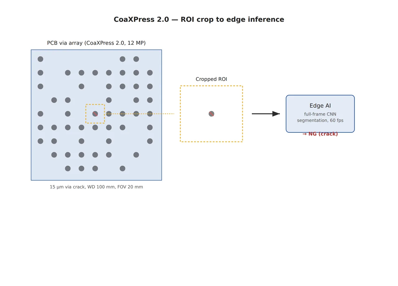
Example. Under the same 12MP/60fps condition, if the edge crops and transmits only candidate-defect regions (e.g., one to three 512×512-pixel ROIs per frame), effective transmission volume can drop to under 1/20 of the original, in some cases making 1GigE sufficient. However, this holds only on the premise that “the edge model does not miss a region where a defect might exist” — if the edge model’s recall is low, this can actually increase missed detections.
Point. An edge AI camera is closer to “shifting” the bandwidth problem than “resolving” it — the bottleneck merely moves from the cable to the edge model’s recall, so it cannot be concluded that software image processing alone can fully cover the physical limits of the hardware interface.
Core framework matching table
Using a via-hole crack on multilayer PCB (an opaque copper-foil surface with low diffuse reflectance and some specular reflection mixed in) as the reference inspection target, the achievable detection conditions by interface are summarized below.
| Interface | ① Minimum detectable defect size (µm) | ② Optical setup (lighting/lens, WD) | ③ Algorithm parameters |
|---|---|---|---|
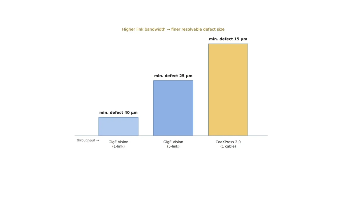
| GigE Vision (single 1GigE) | 40 µm (relaxed due to resolution constraint) | 5MP, coaxial epi-illumination, WD 100 mm, FOV 25 mm | 15 fps, single-frame threshold binarization |
| GigE Vision (multiple 5GigE links) | 25 µm | 8MP, coaxial epi-illumination + low-angle ring combined, WD 100 mm, FOV 25 mm | 30 fps, CNN classification after ROI crop |
| CoaXPress 2.0 (single cable) | 15 µm | 12MP, coaxial epi-illumination, WD 100 mm, FOV 20 mm | 60 fps, full-frame CNN segmentation |
Requires confirmation: the illuminance (lx) and exposure-time values in the table above vary with the actual measured reflectivity of the target copper-foil surface, so this table does not present them as fixed figures. They require separate confirmation by sample testing before actual line application.
What the table shows is clear. In the GigE Vision family, bandwidth pressures resolution down, and the minimum detectable size settles for a compromise in the 25–40 µm range, whereas CoaXPress 2.0 opens room to push resolution up to the 15 µm class under the same FOV and WD conditions. This is per single camera, however, and it must be considered separately that as the camera count rises, the frame-grabber and cabling cost on the CoaXPress side rises along with it.
A note on comparison — conditions favoring the opposite approach
For a line with eight or more cameras where each camera’s required resolution is relatively low, 40 µm or coarser (for example, large-defect or foreign-matter inspection of an injection-molded part’s exterior), GigE Vision’s wiring simplicity and long-distance transmission advantage can be more favorable in terms of total cost of ownership (TCO) than CoaXPress 2.0’s high bandwidth. Likewise, in a structure where an edge AI camera completes first-pass screening and only suspect frames are sent to the upstream system, the interface’s own bandwidth requirement drops significantly. However, this judgment depends on the target’s surface material and reflectivity and on the actual defect distribution, so it cannot be confirmed before sample testing.
Field Checkpoints
- Is WD (working distance) secured? — Confirm that 100 mm WD is maintained even after a camera or lens swap, and that there is no interference with the lighting module.
- Has the target inspection line’s required ‘resolution × frame rate’ value been calculated, and has the chosen interface’s effective bandwidth (single/multiple GigE, CoaXPress 2.0, etc.) been verified in advance to meet it?
- When adopting an edge AI camera, has the edge model’s recall been separately validated — is the edge judgment being trusted without full review of the raw data?
- Has the reflectivity of the target copper-foil/resin surface been measured? — If lots with severe diffuse reflection are mixed in, the lighting conditions in the matching table cannot be applied as-is.
References and Existing Patents
- CoaXPress 2.0 specification: up to 12.5 Gbps per single cable, up to 50 Gbps in a multi-cable configuration (VA Imaging, Adimec technical materials)
- USI AI Smart Camera solution announcement, 2026-09-08 (PR Newswire, IoT Tech News)
- TDK SensEI edgeRX Vision (2,000 parts/min, detects defects down to 1 mm×0.5 mm) and the expanded edgeRX PRO sensor module, 2026-08 (TDK Electronics, Edge AI and Vision Alliance)
- US11493901B2, “Detection of defect in edge device manufacturing by artificial intelligence,” Assignee: International Business Machines Corporation (IBM)
- US12211195, “Edge defect detection via image analytics,” Assignee: Applied Materials, Inc.
- US7889234B2, “Automatic calibration for camera lens distortion correction,” Assignee: Delphi Technologies Inc. (now Aptiv Technologies AG)
- US11386522B2, “Calibration of individual and arrayed cameras using images and video,” Assignee: Reification Inc.


You May Also Like
What Should a Camera See When a Humanoid Grasps an Object?
Four Snags in Initial Jetson Orin Nano Setup