The Tug-of-War Between Distortion Correction and Depth of Field: How Telecentric Lenses Catch Micro-Defects Without Losing Them
Step up the magnification on an inspection lens by one notch, and a micro-crack or solder bridge that the camera couldn’t previously catch finally comes into focus. But if a single component’s height varies by just 0.3 mm on the same line and that same defect blurs out again, the problem isn’t the lens’s resolving power — it’s depth of field (DOF). The higher the magnification, the narrower the in-focus range becomes, and once the lens’s own distortion is layered on top of that, not just defect detection but the dimensional measurement values themselves start to drift.
Leaving this unaddressed leaks cost in two ways. One is that a defect gets captured blurred in an out-of-focus region and goes straight through as a missed detection. The other is that a dimension measured on an uncorrected, distorted frame diverges from its true value, falsely flagging good product as defective. In both cases the root cause is the same: magnification, DOF, distortion, and reflectivity — four variables — were treated separately at the lens-selection stage. This article organizes, centered on telecentric lenses, how these four variables are entangled with each other, and the criteria for deciding whether to correct distortion optically or in software.
Why depth of field narrows as magnification increases
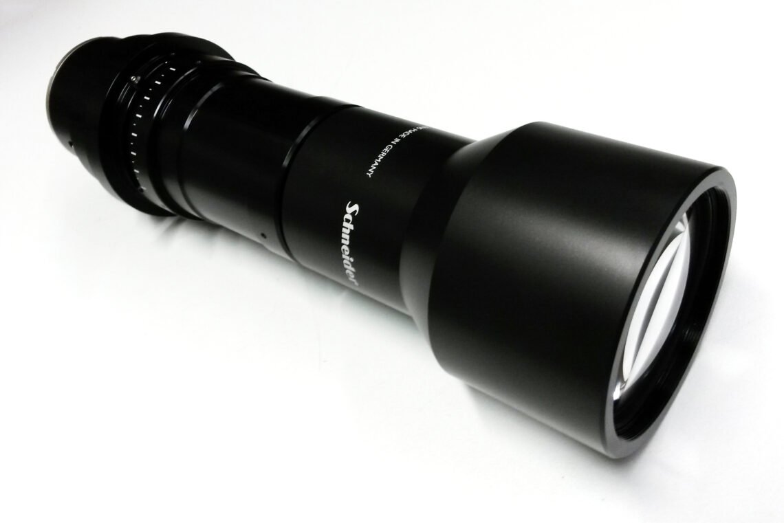
With an ordinary lens, image size (magnification) and perspective both change together with distance to the target, but a telecentric lens keeps its chief ray parallel to the optical axis, so magnification stays nearly constant even as the target moves forward or backward within the working-distance (WD) range. This property makes it possible to obtain values close to a part’s true dimensions, without perspective distortion, even when measuring a component with a three-dimensional shape.
The problem is that this advantage isn’t free. The higher the magnification an inspection requires, the more finely a micro-defect needs to be resolved — and raising magnification to increase resolving power narrows the in-focus depth range (DOF) by a corresponding amount. Extended-DOF optical systems ease this trade-off through approaches such as a multi-focal-length lens structure or deliberately leaving a controlled amount of spherical aberration, but even with designs like these, "high magnification + wide DOF" cannot both be secured without limit at the same time. In the end, the first step is confirming whether the inspection target’s height variation falls within the lens’s effective DOF, and if that variation exceeds it, a trade-off is needed — either lowering magnification or reducing the height variation itself through lighting or a fixturing jig.
Distortion correction: fix it optically, or fix it in software?
Lens distortion splits into radial (barrel or pincushion) and tangential types, and it shows up as straight edges appearing to curve on screen, which directly affects measurement accuracy and the reliability of automated inspection. Because distortion shifts only geometric position without reducing an image’s brightness or sharpness, a substantial portion of it can be reversed through software correction. In fact, pre-processing-stage distortion-correction solutions that add no CPU load and don’t affect frame rate are already commercially available.
That said, it is difficult to say that software correction alone can fully cover the fundamental limits of a hardware optical setup. In applications like precision dimensional measurement, where a pixel-level error translates directly into an out-of-spec result, industrial practice still favors a configuration that selects, as the primary measure, a lens with optically minimized distortion (such as a telecentric lens), and treats software correction only as a secondary means of refining the residual error. In inspection requiring coordinate-measuring-machine (CMM)-grade precision, there are established cases where a separate procedure for correcting the measurement error caused by lens distortion itself has become standard practice. In other words, the approach of "just fix all the distortion in software" holds up at the level of ordinary visual inspection, but it is difficult to apply as-is to precision measurement inspection with tight dimensional tolerances.
How reflectivity by material affects lens and WD selection
Even within the same inspection station, a highly reflective region like the exposed copper pads on a PCB assembly and a diffuse-reflection-dominated region like the matte surface of an injection-molded housing call for different lens characteristics. On a highly reflective metal surface, contrast is extremely sensitive to lighting angle — no matter how good the lens’s distortion and DOF design is, the defect itself gets buried in specular glare once the lighting condition is off. A recently published review of highly reflective metal-surface defect detection likewise points out, as a common finding, that general-purpose detection models lose adaptability as scale variation grows and defect shapes become more irregular. The case of an improved YOLOv8-family model specialized for aluminum-profile surface defect detection (CDA-YOLOv8), which added a multi-scale feature-extraction module and raised mAP@0.5 from 83.7% to 88.1%, likewise shows that on materials with difficult reflectivity, a separate correction is ultimately needed on the algorithm side as well.
When selecting a lens, this reflectivity variation also needs to be reflected in the WD margin. To leave room for adjusting the lighting angle on a highly reflective region, the WD needs to be secured from the start so that the lens barrel and the lighting head don’t physically interfere with each other. If WD is insufficient and only the lens gets swapped for a higher-magnification one, you later run into a situation where there is physically no room to adjust the lighting angle even if you want to.
Core framework matching table (example setup)
The table below is an example setup for inspecting solder bridges and micro-cracks on a PCB connector assembly together with surface scratches on the adjacent injection-molded housing. Actual parameters vary by target material, defect type, and required tolerance, so confirmation is required before finalizing any spec.
| Category | Item | Value / Spec |
|---|---|---|
| ① Minimum detectable defect size | Solder bridge/micro-crack baseline | 20 µm (example baseline, requires re-verification per target) |
| ② Optical setup — lens | Lens type | Bi-telecentric lens, distortion rating 0.1% or lower |
| ② Optical setup — WD | Working distance | WD 65 mm secured (including margin for lighting-angle adjustment, example) |
| ② Optical setup — DOF | Effective depth of field | Within ±0.3 mm (requires advance confirmation that the target’s height variation does not exceed this range) |
| ② Optical setup — lighting | Reflectivity response | Highly reflective copper-pad region: low-angle dark-field / matte injection-molded region: diffuse dome illumination in parallel |
| ③ Algorithm parameters | Distortion correction | Primary optical correction + software correction of residual distortion (calibration-grid based) |
| ③ Algorithm parameters | Defect classification model | YOLO family with multi-scale feature extraction applied, reflective regions trained as a separate class |
What this matching table shows is that the decision to raise lens magnification to match defect size creates a new path to missed and false detections by itself, unless the remaining three variables — DOF, distortion, and reflectivity — are reviewed at the same time. Advancing magnification alone leaves DOF shrinkage or specular interference as a bottleneck.
A reservation on materials with difficult reflectivity
On materials with heavy diffuse-reflection variation — high-gloss metal, a wet-coated surface, or a surface still carrying polished mold marks — it is often difficult to apply the lighting-lens combination in the matching table above as-is. For these materials, a procedure of first checking each lens-lighting combination’s response on actual samples is required, and before sample testing, it cannot be confirmed that a specific lens or distortion-correction method is always effective on a specific defect.
By comparison, for an inspection with large target height variation and low magnification requirements (e.g., full-surface appearance inspection of finished product), a combination of an ordinary lens’s wide DOF with software distortion correction can actually be more favorable than a telecentric lens’s narrow DOF. Which side is favorable has to be judged by weighing defect size, dimensional tolerance, and target height variation together.
Field Checkpoints
- WD (working distance) secured: telecentric lenses often have a large barrel diameter, so advance confirmation is needed that WD allows adjusting the lighting angle per reflectivity without physically interfering with the lighting head.
- Measure whether the target’s height variation (including part tolerance and jig repeatability) falls within the lens’s effective DOF range.
- If distortion correction relies on software alone, confirm that the required dimensional tolerance falls within the residual error remaining after that correction.
- For heavily diffuse-reflecting regions, do not finalize the lens-lighting combination before sample testing.
References (Sources)
- Towin, “Industrial Lens Selection Guide 2026” — towinlens.com
- Basler AG, “Lens Geometric Distortion Correction” — baslerweb.com
- Vision Systems Design, “Telecentric lenses focus on machine vision” — vision-systems.com
- STEMMER IMAGING, “Telecentric Lenses (Machine Vision)” — stemmer-imaging.com
- ScienceDirect, “A review of vision-based defect detection research for highly reflective metal surfaces” (2026) — sciencedirect.com
- MDPI Processes, “Applications of Deep Learning to Metal Surface Defect Detection: Status and Challenges” — doi.org
- Teledyne DALSA, “Camera Link HS and CoaXPress Machine Vision Connectivity Standards Explained” — teledynedalsa.com
- Electronics Weekly, “Machine vision for robots, vehicles and construction equipment” — electronicsweekly.com
- Security Informed, “IDS Unveils uEye Camera Platforms At VISION 2026” — securityinformed.com
- arXiv, “Towards Object Segmentation Mask Selection Using Specular Reflections” (2026) — arxiv.org
Note (patents, verify original text on Google Patents): US6324016B1 “Telecentric lens”, US7336430B2 “Extended depth of field using a multi-focal length lens…”, US8681224B2 “Method for high precision lens distortion calibration and removal”, US7769556B2 “Method for correcting measuring errors caused by the lens distortion of an objective”, US10176588B2 “System and method for specular surface inspection”


You May Also Like
Machine-Vision Inspection: Physics Comes Before Software
Keeping Frame Rate and Lighting from Colliding on a High-Speed Inspection Line