Keeping Frame Rate and Lighting from Colliding on a High-Speed Inspection Line
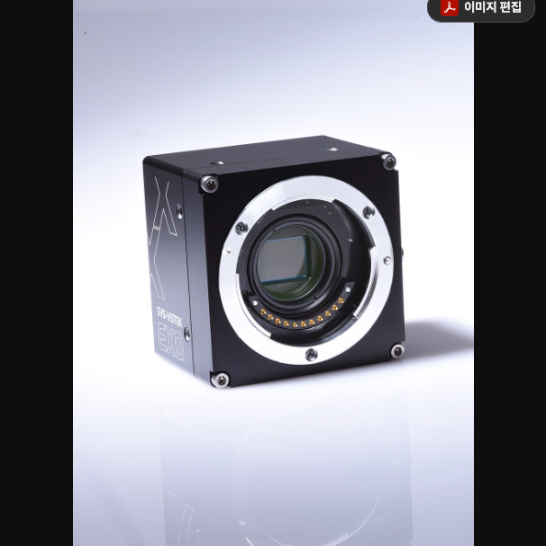
To carry out full-surface inspection for surface defects on a fast-moving production line like a PCB or display panel, the camera’s frames-per-second first has to be raised to match line speed. The problem is that the moment frame rate goes up, the exposure time allowed per frame shrinks, and the amount of light reaching the sensor drops right along with it. Leave this unaddressed, and a micro-scratch or foreign-matter defect gets buried in background noise within a blurry, low-contrast image — and defective product ends up leaking straight through to downstream processes and shipment, coming back as recall costs and lost trust. The recent string of announcements for high-performance area-scan cameras equipped with 4-channel CoaXPress-12 interfaces also reads as a sign that demand for this kind of high-volume, high-speed image processing is genuinely growing in the field. The solution isn’t raising the spec of a single camera — it’s aligning lighting, interface, and trigger timing into one system.
Why surface material and reflectivity need to be checked first
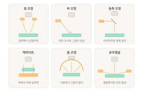
Before finalizing lighting and lens specs, the inspection target’s surface material and reflectivity always have to be identified first. Under the exact same illuminance, the amount of reflected light reaching the camera and the diffuse-reflection pattern come out completely different depending on whether the target is a matte injection-molded part, a glossy coated surface, or a PCB with exposed metal traces. For example, a target with strong specular reflection, like a display panel’s glass surface, can get sharp defect contrast with coaxial illumination, but a target with rough surface texture and heavy diffuse-reflection variation, like an injection-molded part, often fails to reproduce the same result under the same lighting angle — so it cannot be confirmed that a specific lighting condition will work until it has been pre-tested on actual production surface samples. Checking each material’s reflective characteristics first, before settling the lens and algorithm parameters, is what decides whether the system succeeds.
The physical trade-off among frame rate, exposure time, and illuminance
In high-speed inspection, the moment frame rate goes up, exposure time and illuminance both need to be redesigned together. A shorter exposure time reduces the total light reaching the sensor, lowering the signal-to-noise ratio, which in turn degrades contrast and crushes the boundary of a micro-defect. For example, take a line where 30 fps with 5,000 lx lighting was enough, and push it to 120 fps: to maintain the same image quality you either need to raise illumination intensity significantly or open the aperture — and opening the aperture too far shallows depth of field, creating regions where focus drifts off on a molded part’s surface with fine curvature. In the end, speed, light, and depth all eat into each other, so it’s safer to fix the target defect size and line speed first and work backward from there.
What expanded bandwidth opens up: securing FOV and resolution at once
When per-channel bandwidth widens, as with CoaXPress-12, there’s room to raise capture speed while keeping high resolution. With older interfaces, raising resolution increased the data volume being transmitted, sacrificing frame rate in the process, but with generous bandwidth and multi-channel synchronization, the actual area covered per pixel can stay tight even within a wide FOV. That said, bandwidth is purely a transmission matter, and it needs to be noted separately that it means nothing if the actual lens and lighting can’t optically reproduce that resolution.
Strobe synchronization: the blur one misaligned frame creates
In ultra-high-speed capture, the key to suppressing motion blur isn’t continuous lighting — it’s strobe illumination that fires an intense burst instantaneously, synchronized with the shutter down to the microsecond. The faster the line speed, the further the target travels during the exposure window, so if the trigger signal is even slightly misaligned between camera and lighting, the defect boundary smears and gets recognized as larger or blurrier than it actually is. This timing error is difficult to fully correct afterward with an algorithm.
| Category | Reference baseline (example) |
|---|---|
| ① Minimum detectable defect size | Roughly 30 µm for micro-scratches/foreign matter (adjusted in the 20–50 µm range depending on line speed and surface material) |
| ② Optical setup | High-brightness strobe illumination (microsecond flash; mandatory pre-testing on samples for materials with heavy diffuse reflection), low-distortion FA lens with 25–35 mm focal length, WD (working distance) of 150 mm or more secured |
| ③ Algorithm parameters | ROI around 512×512 px, per-frame processing-time threshold within 8 ms, contrast-threshold-based defect-candidate filtering |
The figures above are general reference baselines assuming a situation of full-surface inspection for µm-class defects on a high-speed line, not the official spec of a specific product. In actual application, lighting angle, exposure time, and ROI size need to be re-tuned through reflectivity testing per surface material.
Field Checkpoints
- Has the inspection target surface’s material and reflectivity been pre-tested on actual production samples?
- Are the minimum exposure time and illuminance (lx) required at the target line speed physically achievable?
- Is the WD (working distance) required by the selected lens’s focal length actually achievable within the installation space?
- Is trigger timing between the strobe illumination and camera shutter synchronized down to the microsecond?
- When adopting expanded bandwidth (e.g., CoaXPress-12), does multi-channel synchronization error avoid affecting inspection accuracy?


You May Also Like
Dark-Field Illumination and Edge AI Defect Classification: A New Baseline for Specular-Surface Inspection
There Are Defects That Vanish in Visible Light — Inspection Design Beyond the 1 μm Barrier in SWIR Imaging