When Height Varies, F7.1 Beats F16 on a Telecentric Lens
OPTICS
With height wobbling ±0.15 mm, the working F-number that protects the contrast of a 20 μm defect is 7.1, and closing down to 16 costs contrast.
Looking at solder bridges and pin pitch on an SMD connector with a telecentric lens, I calculated the contrast that height wobble allows and the position error that distortion creates.
About 11 min read
Raise the magnification of an inspection lens by one step and fine cracks and solder bridges that were invisible finally come into focus. The targets are the solder joints of an SMD connector mounted on a board and the matte housing beside them. Solder is a strongly glossy curved surface whose highlights wander with the lighting angle, and the housing is black PBT resin with an assumed diffuse reflectance of around 5 %. The defect to find is a solder bridge 20 μm wide, and the same image is also used to measure the connector pin pitch against a ±25 μm tolerance. Board warp and component seating differences are assumed to make the inspected surface wobble by ±0.15 mm, 0.3 mm in total.
When height wobbles, two things go wrong at once. Bridges blur where focus slips and escape as misses, and with an ordinary lens the magnification shifts with height, so pin pitch is measured differently from reality. The first is the cost of shipping defects, and the second is the cost of scrapping good connectors as defective. Trying to solve both with one lens choice is what sets magnification, depth of field and distortion into a tug-of-war.
I break the tug-of-war into three numbers: magnification error with height, contrast at the defect frequency (MTF1), and the position error that distortion creates. The camera is assumed to be 4,096 × 3,000 px with 3.45 μm pixels, and the lens a telecentric2 design at 0.6 magnification. One pixel covers 5.75 μm on the part, the field of view is 23.55 × 17.25 mm, and a 20 μm bridge spans 3.5 pixels.
Two things a 0.3 mm height change alters
An ordinary lens (entocentric3) images near objects larger and far objects smaller. The rate of magnification change is approximately height change ÷ working distance, so at a WD of 100 mm a 0.3 mm height change alters magnification by 0.3 %, and a point at the edge of the field (11.8 mm from center) moves 35.3 μm, or 6.1 pixels. With a pin-pitch tolerance of ±25 μm, a 35 μm position shift makes the measurement meaningless. Stretching the WD to 200 mm still leaves 17.7 μm.
A telecentric lens removes this problem by making the chief rays parallel to the optical axis. Assuming the angle between chief rays and the axis, the telecentricity, is 0.1°, the sideways shift at a 0.3 mm height change is 0.3 mm × tan 0.1° = 0.52 μm. A Vision Systems Design article likewise explains that telecentric lenses keep magnification constant over a defined depth of field. What this lens removes, though, is magnification error, and the blurring of focus stays exactly where it was.
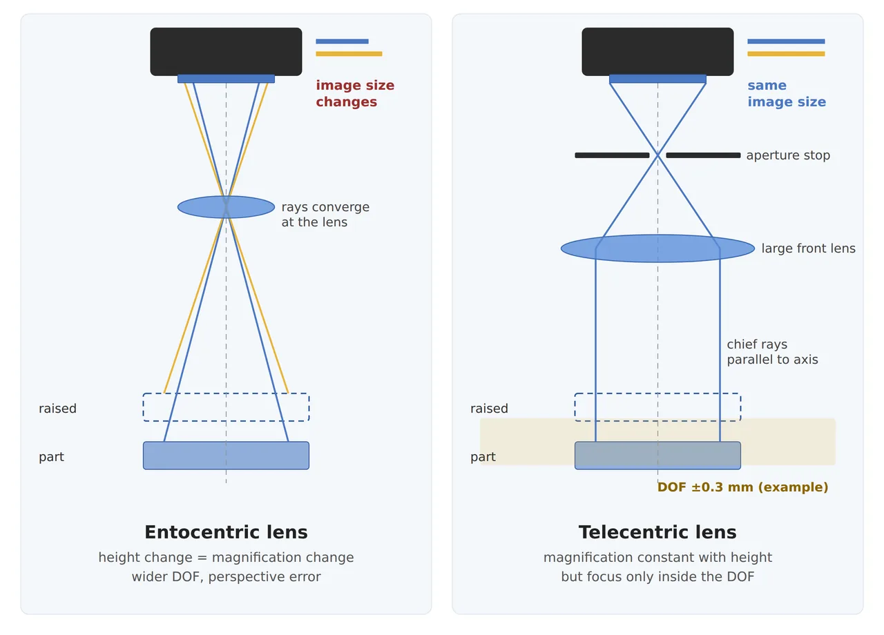
The figure compares, side by side, an ordinary lens whose chief rays converge into the lens so image size changes with part height, and a telecentric lens whose chief rays run parallel to the axis so image size stays the same. The telecentric side also marks a separate in-focus range of ±0.3 mm, and the price of getting that range is the subject of the next calculation.
The diffraction the DOF formula leaves out
The common geometric depth-of-field4 formula is 2 × working F-number5 × allowed blur ÷ magnification². With the allowed blur set at 2 pixels on the sensor (6.9 μm), it gives 0.31 mm at a working F-number of 8 and 0.61 mm at 16, so the ±0.3 mm in the figure comes from around F16. Judging by the formula alone, closing the aperture looks ever safer. It is an illusion. The term missing from this formula is diffraction6. Closing the aperture widens the spread of light, so contrast falls even where focus is perfect.
Treating the 20 μm bridge as one half-period of a bright-dark pair puts the object-side spatial frequency at 25 lp/mm. Approximating contrast at this frequency as the MTF left by diffraction multiplied by the MTF left by defocus, a working F-number of 16 (object-side NA7 0.0187) gives 54 % even where focus is perfect, 22 gives 39 %, and 32 gives 16 %. By my calculation, the aperture with the highest MTF at the extremes of the ±0.15 mm height wobble is an object-side NA of 0.042, a working F-number of 7.1 at 0.6 magnification, where the MTF is 70 %. The wide depth bought by closing to F16 trades 70 % at the height extremes for 54 % at the very center of focus.
70%
Best MTF reachable at the ±0.15 mm height extremes (25 lp/mm)
54%
MTF in perfect focus at a working F-number of 16
0.52μm
Position error from a 0.3 mm height change at 0.1° telecentricity
A number that stays put as magnification rises
Magnification does not enter this calculation. Evaluated on the object side, diffraction and defocus leave a contrast set only by object-side NA and height wobble, and magnification changes only how many pixels share that contrast. Raising magnification from 0.6 to 1.2 increases the pixels across a bridge to 7, but the best MTF at the ±0.15 mm height extremes is still 70 %. Keeping the same NA requires the working F-number to rise to 14.2, and the field of view halves to 11.8 × 8.6 mm.
That is why I choose a lens in two steps. First, set the magnification so the defect spans at least three pixels; next, calculate the object-side NA with the highest contrast for the height wobble and fix the lens aperture as working F-number = magnification ÷ (2 × NA). For this connector, that is 0.6 magnification and a working F-number of 7.1. If the height wobble grows to ±0.3 mm, the optimal NA drops to 0.0275 and the best MTF falls to 55 %, barely meeting my criterion of 50 % or more at the defect frequency. Beyond that, holding height down with a fixture costs less than changing lenses.
Distortion can be undone, height cannot
Distortion8 is a geometric error that images straight edges as curves. Assuming 0.1 % distortion, a point in the corner of the field (14.6 mm from center) shifts 14.6 μm, or 2.5 pixels. That is too large to leave alone in an inspection that must measure pin pitch at 5 μm resolution, but distortion only moves positions without losing brightness, so calibrating with a grid target9 of known dot spacing undoes most of it. My criterion is to keep the position error left after correction below one pixel (5.75 μm).
Where to run the correction is a question of processing time. The Basler material notes that correcting in PC software can raise CPU load by 40 % and halve the frame rate, and explains that correcting inside the camera has no impact on CPU load or frame rate. Height is another story. The height-dependent magnification change of an ordinary lens does not straighten out with this kind of correction. The correction table is built at one height, while the magnification error changes with each part’s height, so unless height is measured separately, software has no way of knowing it. That is the reason to choose telecentric for measurement inspection.
Here are the three numbers in one table. The lens WD is assumed to be 65 mm per the bi-telecentric spec, and the front element must be larger than the 29.2 mm field diagonal to keep the edges from being cut off.
| Inspection item | ① Minimum defect size | ② Optical setup · WD | ③ Algorithm parameters · in plain words |
|---|---|---|---|
| Solder bridge | 20 μm = 3.5 pixels (5.75 μm on the object) | 12 MP with 3.45 μm pixels, bi-telecentric 0.6, field of view 23.55 × 17.25 mm, WD 65 mm (lens spec assumed), object-side NA 0.042 (working F-number 7.1) | MTF 70 % at 25 lp/mm at the ±0.15 mm height extremes (diffraction MTF × defocus MTF approximation), criterion 50 % or more |
| Connector pin pitch | Tolerance ±25 μm → measurement resolution 5 μm | Distortion 0.1 % (assumed) → 14.6 μm (2.5 pixels) in the corner; telecentricity 0.1° (assumed) → 0.52 μm over 0.3 mm height | Grid calibration to keep residual position error at 1 pixel (5.75 μm) or less, correction inside the camera or frame grabber |
| Larger height wobble | 20 μm | At ±0.3 mm, optimal object-side NA 0.0275 (working F-number 10.9) | Best MTF 55 %, barely meeting the criterion → reduce height variation with a fixture or take two focus positions |
Reading the three rows together, a telecentric lens protects measurement by cutting height-dependent magnification error to 0.52 μm, while defect contrast is set separately by object-side NA and height wobble. Writing the working F-number on the same line as magnification and distortion when choosing a lens keeps both ends of the tug-of-war in view.
Inspections where an ordinary lens does better
Telecentric is not always the answer. Once the field of view passes a few tens of mm, the front element has to be larger than the field, making the lens big and expensive and leaving less room for lighting. For inspections that only check presence or large defects without measuring dimensions, or where height wobble is large and magnification low enough that magnification error stays far below the tolerance, an ordinary lens with software distortion correction is more practical. Conversely, when positions of points at different heights must be measured, as with pin pitch, telecentric has the advantage. How cleanly a bridge separates from highlights on strongly glossy curved solder depends on lighting and surface condition, so it cannot be guaranteed before a sample test.
A telecentric lens tends to be larger and more expensive than an ordinary lens with the same field, but a fair quote sets that against the cost of scrapping good connectors because of wrong measurements. If, as calculated above, the 35 μm error of an ordinary lens at 100 mm WD exceeds the whole tolerance, the price difference belongs side by side with the cost of misjudgments. This article explains technology and is not investment advice. See our Disclaimer.
Field Note
Choosing a lens for this connector, I would measure the height distribution of the inspected surface before reading any datasheet. Measuring joint heights on 20 boards to learn how many mm they wobble lets me calculate the optimal NA and working F-number straight from that value. Once the lens is chosen, I place a grid target at nine points across the field and at three heights (−0.15, 0, +0.15 mm) and record position error and sharpness together. If the brightness difference of a bridge at the height extremes falls below 70 % of the value at the center of focus, I revisit the aperture calculation.
Field Checkpoints
Once the height-distribution measurement and the grid-target log have confirmed the assumptions behind the calculations, answer the questions below.
- Does the lighting fit within the 65 mm WD, and is the front element larger than the 29.2 mm field diagonal?
- Have you measured the actual height wobble of the inspected surface and calculated the optimal object-side NA? (At ±0.15 mm, NA 0.042, working F-number 7.1)
- Before closing the aperture to widen depth, have you checked MTF at the defect frequency? (At F16, 54 % even in focus)
- Is the position error left after grid calibration below one pixel (5.75 μm)?
- If there are measurement items, have you calculated the height-dependent magnification error from the telecentricity?
- Have you checked bridges on strongly glossy curved solder with real samples?
Frequently Asked Questions
Does a telecentric lens give more depth of field?
No. A telecentric lens only keeps magnification from changing within the depth of field; the depth itself is set by object-side NA on the same principle as an ordinary lens. The STEMMER IMAGING lens guide likewise states that depth of field at the chosen F-number must cover the part tolerance without pushing diffraction too far.
Where is the best place to correct distortion?
For processing speed alone, correcting inside the camera or frame grabber puts less load on the PC. For measurement inspection, whether the residual error falls within the measurement resolution matters more than where the correction runs. I recommend placing a grid target at nine points across the field and measuring position error before and after correction.
Glossary
- [1] MTF MTF
A measure of how much bright-dark contrast a lens preserves at each spatial frequency. The text evaluates it at 25 lp/mm, which corresponds to a 20 μm defect. ↩ - [2] Telecentric lens telecentric optics
A lens whose chief rays run parallel to the axis, so magnification stays nearly the same as height changes within the focus range. Its front element must be larger than the field. ↩ - [3] Entocentric lens ordinary lens
An ordinary lens whose chief rays converge toward the lens. Nearer objects image larger, so magnification changes with height. ↩ - [4] Depth of field DOF
The front-to-back range on the object side that counts as in focus. The geometric formula leaves diffraction out. ↩ - [5] Working F-number effective f/#
The F-number under actual imaging conditions. It links to object-side NA as working F-number = magnification ÷ (2 × NA). ↩ - [6] Diffraction diffraction limit
The spreading of light at the edge of an aperture. The more the aperture closes, the wider the spread, so contrast drops even in focus. ↩ - [7] NA NA
A number giving, as a sine, the half-angle of the light cone a lens accepts. Object-side NA sets contrast and depth together. ↩ - [8] Distortion radial distortion
A geometric error that images straight lines as curves. It moves positions without losing brightness, so calibration undoes most of it. ↩ - [9] Grid target dot grid
A plate printed with dots or lines at precise spacing. Comparing imaged positions with the true spacing builds the distortion correction table. ↩
References
- Basler, Lens Geometric Distortion Correction (in-camera correction with no CPU load or frame-rate impact; software correction can raise CPU load by 40 % and halve frame rates)
- STEMMER IMAGING, Telecentric lenses (chief rays parallel to the axis, larger fields need larger front elements, depth of field at the chosen F-number must cover the part tolerance without pushing diffraction too far)
- Andrew Wilson, Telecentric lenses focus on machine vision, Vision Systems Design (2004, constant magnification over a defined depth of field, front optics larger than the field)
- Edmund Optics, Introduction to Modulation Transfer Function (MTF definition and cutoff frequency ξc = 1 ÷ (λ × f/#))
- Formulas: magnification change rate ≈ height change ÷ WD, telecentric position error = height change × tan(telecentricity), geometric depth of field = 2 × working F-number × allowed blur ÷ m², object-side NA = m ÷ (2 × working F-number), diffraction MTF = (2/π)(arccos x − x√(1 − x²)) with x = ν ÷ (2NA ÷ λ), defocus MTF = |2J₁(πbν) ÷ (πbν)| with b = 2 × NA × height change, contrast ≈ product of the two MTFs (λ = 0.55 μm, ν = 25 lp/mm), distortion position error = distortion × half diagonal
Related reading — Can One Focus Plane Keep Parts of Every Height Sharp? · What Optical Design Needs to Not Miss Defects on a High-Speed Line · A Machine Vision Lens Calculator That Catches the FOV Error a Shortcut Formula Misses

Noctvision
An engineer who has handled mechanical design and project management for production equipment since 2005. Here I work through the cameras, lenses and lighting that go into equipment with formulas and public data, and record the assumptions and sources alongside the numbers.


You May Also Like
In SWIR Imaging, Lighting and Aperture Keep the Defect Contrast
How 3D Structured Light Measures a Solder Lead Lift That Brightness Cannot Show