A Light Field Camera Trades Pixels for Depth
OPTICS
A light field camera bundles the pixels behind each lens into one point of the picture, and buys height with them.
Viewing a 25 μm gold wire at 2x, I calculated how the bundle size splits the wire width, the focus range and the height resolution between them.
About 16 min read
If a picture from a 4,000 × 4,000 px sensor came back as a 292 × 292 point image, you would suspect a fault first. The handheld light field camera1 prototype built at Stanford in 2005 gave exactly that number. Of its 16 million pixels, 0.53 % survived as points of the picture, and the rest went into recording which part of the lens the light had passed through. In return the camera moves its focus after the shot and reads height from a single frame.
The camera from photonicSENS that won the VISION Award on 7 October at VISION 2026 in Stuttgart stands on the same principle. The company says it puts a microlens array2 between lens and sensor to catch many directions in one frame, and delivers depth for every pixel with no projector and no scan axis. It named wire bond inspection in semiconductor packaging as its core market, and a caption in the finalist article says it measures wire bond height to better than 10 μm.
The target here is a 25 μm gold wire joining a chip to its board. The wire is a round mirror, so a thin white line of specular reflection3 stands on the side the light hits, while the solder resist below is a matte surface that scatters light back. If a sagging loop or a broken wire slips through on a screen where reflectance splits like this, the board is caught only at functional test or goes into the box as it is. So when I hear that one shot also holds height, I count samples first. The first calculation is whether a 25 μm wire is still on screen after some pixels have been given to depth.
Pixels behind one lens see one point from many directions
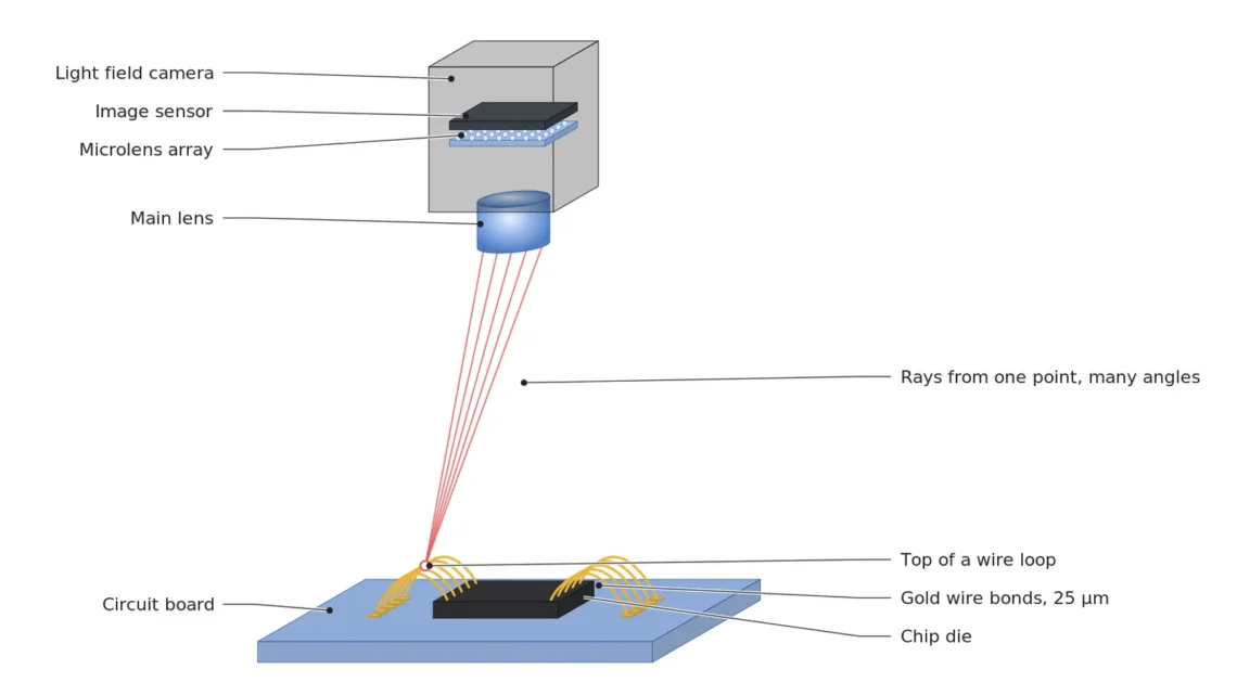
One pixel in an ordinary camera takes light from the whole lens opening and mixes it. Light through the top edge of the lens and light through the bottom edge pile into the same pixel, so the direction the light came from is erased right there. A light field camera puts a microlens array where the main lens forms its image and sets the sensor just behind it. Each small lens takes one point of the picture, and the pixels laid behind it each look back at a different patch of the main lens opening.
Picture looking into a room through several keyholes cut in one door. Each keyhole shows almost the same scene, but how the near chair overlaps the far wall shifts a little with the position of the keyhole. The pixels behind one small lens are those keyholes, and the size of the shift is the clue to height. Ng’s 2005 report notes that for these keyhole images to fill the pixels without overlapping, the main lens and the microlenses must share the same f-number4. The calculation below sets both to f/8.
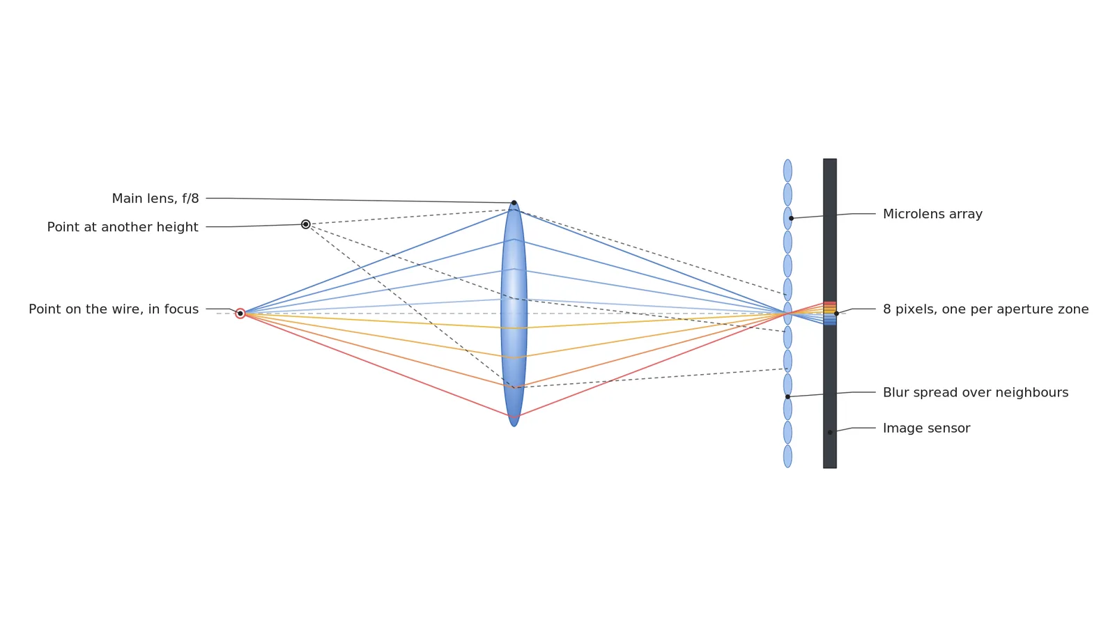
The eight rays from the red point on the left pass eight zones of the main lens, meet again at one microlens and split onto eight pixels behind it. It is worth noticing that the order is reversed, so light through the upper zone lands on the lower pixel. Light from the black point at a different height cannot meet at one point on the lens array and spreads over several neighbouring lenses. Undoing that spread pattern to compute height is how this camera estimates depth.
If one small lens covers N pixels each way, the points of the picture shrink to 1/N². Ng’s prototype laid 296 × 296 lenses of 125 μm over 9 μm pixels and got a spatial resolution of 292 × 292 with just under 14 × 14 directional samples. Sixteen million pixels shrinking to 85,264 points is what the 0.53 % means. When I receive a light field camera spec sheet, I look for N before the pixel count. That one number sets both the width the picture can resolve and the breadth of the focus.
At 2x on a gold wire, the gap from 4.83 to 7.25 is empty
Let me follow in numbers what N decides. The sensor is 4,096 × 3,000 px with 3.45 μm pixels, and I assume a 2x magnification5 lens used at f/8 on the image side. The 25 μm wire diameter and the 200 μm loop height are also assumptions for the calculation. One pixel covers 1.725 μm of the board, and the field of view is 7.07 × 5.17 mm. My standard is to see the wire across at least three samples, so one sample on the board must be 8.33 μm or less, and since one small lens covers N × 1.725 μm, N cannot exceed 4.83.
Focus moves the other way. With a circle of confusion6 of two pixels, 6.9 μm, the depth of field7 of an ordinary camera is 2 × 8 × 6.9 μm ÷ 2² = 27.6 μm. On a manual focus lens barrel, a depth of field scale paired with each f-number sits next to the distance scale, showing which distances stay sharp together between two marks. At 2x the space between those marks shrinks to 27.6 μm, and the top of a 200 μm loop and its bond foot cannot be sharp in one frame.
A light field camera widens that range. Ng’s report says the depth of field of a refocused picture matches a lens with an opening N times narrower, so the range you can refocus over is N × 27.6 μm. Covering the whole 200 μm loop needs N of 7.25 or more. The wire width puts a ceiling of 4.83 on N and the loop height puts a floor of 7.25 under it, so no N meets both.
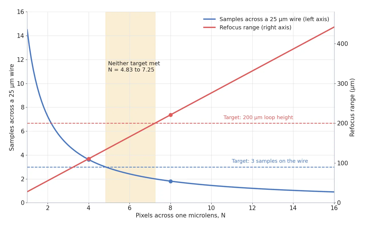
In the chart the blue curve shows samples across the wire falling as N grows, and the red line shows the refocus range rising. A yellow band lies between 4.83, where the blue curve drops below the 3-sample dashed line, and 7.25, where the red line rises above the 200 μm dashed line, and any N outside the band gives up one of the two targets. At N = 4 the wire keeps 3.62 samples but the focus range stops at 110.4 μm; at N = 8 the range reaches 220.8 μm and the wire thins to 1.81 samples.
4.83
Upper limit on N that keeps a 25 μm wire at 3 samples or more
7.25
Lower limit on N that covers a 200 μm loop height in one frame
0.53%
Share of pixels left as picture points in Ng’s prototype
At N = 8 the picture shrinks to 512 × 375 points, 0.19 MP. You buy a 12-megapixel sensor and get a map of fewer than 200,000 points, and what the deal gives you is a height on every point of that map. How fine those heights are is set by another number besides sample size.
Height is split by sample size and the angle of the aperture
Picture the two scenes seen through the far left and far right zones of the lens opening, and the way height is measured becomes clear. The object-side numerical aperture8 is the magnification 2 divided by 2 × f/8, or 0.125, so the two end views look at the wire tilted ±7.18° from vertical. When the loop top rises by Δz, that point moves by 2 × Δz × tan 7.18° between the two scenes, and that movement is the disparity9. Assuming disparity can be read to 0.1 of one lens width, height resolution at N = 8 is 0.1 × 13.8 μm ÷ (2 × 0.126) = 5.48 μm, and 2.74 μm at N = 4. Finer samples give finer heights, so this formula alone makes a smaller N look better in every way. The refocus range from the previous section keeps that illusion in check.
The 5.48 μm at N = 8 sits on the finer side of the 10 μm in the finalist article. The weakest link in my calculation is the number 0.1, though. If disparity can be trusted only to 0.2 of a sample, resolution at the same N = 8 doubles to 10.95 μm and is pushed out to around the article’s figure. A value of 0.1 is what you can expect when the wire surface has texture and the light is even, so until I measure it on a step gauge I keep this number provisional.
The white line on the wire raises another problem. The image of a distant light in a convex mirror does not sit on the surface; it forms half a radius deep, inside the mirror. For a 25 μm wire the image of the white line stands 6.25 μm down, half of the 12.5 μm radius, and the many views of a light field camera follow it like a real point and count height from it. An error larger than the 5.48 μm height resolution can come from one shiny line.
A dome light spreads that line wide and soft. As the line spreads, the point each view follows blurs and the share counted wrong shrinks, but how much of the 6.25 μm remains depends on the wire surface and the size of the dome. How far this error drops on a near-mirror gold wire cannot be guaranteed before a sample test.
Lens array for height, a flat picture for width
There are three ways across the empty band. The first is a design that moves the scale itself. US patent US8290358B1, filed by Adobe’s Georgiev in 2008, covers light field camera designs that give up directional samples for higher spatial resolution. US8619177B2, filed by Raytrix in 2009, mixes microlenses of two or more focal lengths in one array and places the main lens image at a distance that matches none of those focal lengths. Each lens re-images a small piece of the main lens image, so the trade of width for height through a single N changes, and by how much differs from design to design. The more than 50 off-the-shelf designs in the article read as a list placing this scale at different points.
The second way is to measure only near the top of the loop. If the height of the bond foot is fixed separately from a flat picture of the board, the range the light field camera must cover shrinks, and for 110.4 μm N = 4 is enough. The third way is to split the work. Height goes to a light field camera at N = 8, and wire width and breaks at the neck go to one frame from an ordinary camera viewing the same field. I would start with the third way. Tying one number to each judgment makes it easier to tell which side went wrong.
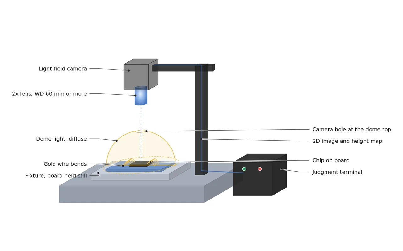
The station in the figure is that third way. A dome light surrounds the board on a fixed fixture, and a light field camera with a 2x lens looks down through the hole at the top of the dome. Because the dome sits between lens and board, the WD10 must be generous compared with the dome height, and I set 60 mm as the lower limit. The judgment terminal receives the flat picture and the height map together and judges loop height and wire width separately.
| Item | Target | Condition · basis | In plain words |
|---|---|---|---|
| ① Minimum defect size (μm) | 25 μm wire at 3 samples or more, loop height range 200 μm | Board sample 8.33 μm or less → N ≤ 4.83 / refocus 200 μm → N ≥ 7.25 | No N keeps both width and height in one frame |
| ② Optical setup · WD | 2x lens at f/8 image side, microlenses f/8, N = 8, dome light, WD 60 mm or more secured | Board sample 13.8 μm, refocus 220.8 μm, field 7.07 × 5.17 mm. Wire width from a separate flat picture (1.725 μm/sample) | The light field handles height and a separate flat picture handles width |
| ③ Algorithm parameters | Disparity estimate 0.1 sample, height resolution 5.48 μm, correction for reflection line depth up to 6.25 μm | End views ±7.18°. At 0.2 sample, 10.95 μm. Reflection image half a wire radius below | Treat the shiny line as sitting a little below the surface and check it on a step gauge |
The first row of the table weighs the most. You cannot give both the wire width and the loop height to one light field camera, and the second and third rows are the way to fill that gap and the assumptions that way leans on. There are clear conditions where an ordinary camera or another 3D method does better. If the height range fits inside the 27.6 μm depth of field, if the board is matte and the field spans tens of mm so projected 3D is easier, or if the inspection only needs to tell whether a wire is there rather than its height, the reason to bring in a lens array weakens. Which one fits better on a shiny gold wire cannot be guaranteed before a sample test, so I suggest shooting both methods side by side on the same board.
The numbers a station picks up once the projector is gone
Bringing in a light field camera removes the projector, the scan axis and on-site calibration. One factory-calibrated camera gives height in one shot, so the station mechanics get simpler and the time a part must stand still shrinks to the length of a single exposure. What takes their place are N, the 0.1-sample disparity and the 6.25 μm of the reflection line. If the spec sheet lists only the pixel count and leaves these three out, you meet a screen where the wire has thinned to 1.81 samples only after the station is built.
Copying these numbers to the front page of the spec sheet falls to the machine vision engineer, whose work spans optical design and inspection criteria. If you are starting out, I suggest taking the 4,000 × 4,000 and 292 × 292 in Ng’s report and working N out backwards. Read from the investment side, the projector and calibration hours go down, while a dedicated lens array, depth computation and in some cases a second camera for flat pictures are added as cost. Which is larger depends on the board’s height range and wire width. This article explains technology and is not investment advice. See our Disclaimer.
Field Note
For this station I place a step gauge of known heights before any wire bonded board. With 10 μm steps at the centre and four corners of the field, I read heights at the N = 8 setting and check the 0.1-sample disparity assumption by whether the readings scatter within 5.48 μm. Then I put a wire bonded board in the same spot and see by how many μm the loop top height changes with the dome on and off. If the difference is near 6.25 μm, I read it as the reflection line pulling the height down.
Field Checkpoints
Once you hold the scatter on the step gauge and the dome on and off difference, what remains is whether the spec sheet and the station can take those numbers. These are the questions to check before ordering.
- Is a WD of 60 mm or more secured with the dome light in place? (whether there is height for the dome between the lens front and the board)
- Does the camera spec sheet state N, the pixels one lens covers, and the spatial sample pitch on the board? (whether the pixel count alone hides how many samples a wire gets)
- Does the loop height range fit inside the N × 27.6 μm refocus range? (220.8 μm at N = 8 under the 2x, f/8 assumption)
- Are wire width and neck breaks checked separately in a flat picture at 1.725 μm per sample? (whether one light field frame cannot hold 25 μm across three samples)
- Has the 0.1-sample disparity assumption been measured on a step gauge? (whether the 5.48 μm height resolution actually holds)
- Has the wire height difference with the dome on and off been checked? (whether the reflection line reads up to 6.25 μm low)
Frequently Asked Questions
Can a picture from a light field camera be refocused later?
It can. The pixels behind each small lens have recorded the direction of the light separately, so shifting pixels along those directions and adding them computes a picture focused at another height. The range has an end, though: by Ng’s report it moves only as far as the depth of field of a lens N times narrower, and beyond that things stay blurred. Under the assumptions above that is 220.8 μm at N = 8.
Do smartphone cameras have a similar structure?
A dual pixel sensor, which splits each pixel into left and right light receiving halves, is a close example. The two halves see the left and right halves of the lens separately, which resembles a very small light field with only two directional samples. This structure is used mainly to focus quickly, and with only two samples it is far from measuring height in μm.
Glossary
- [1] Light field camera plenoptic camera
A camera that records not only how bright the light is but also which part of the lens it came through. It is used to move the focus after the shot or to compute height from a single frame. ↩ - [2] Microlens array MLA
A plate of tiny lenses, tens of μm across, laid out like a grid. In a light field camera each lens takes one point of the picture, and the pixels behind it share out the directions of the light. ↩ - [3] Specular reflection mirror reflection
Reflection in which light leaves a smooth surface in one direction, at the same angle it arrived. The thin white line on a gold wire comes from it. ↩ - [4] f-number F-number
The focal length divided by the diameter of the lens opening. A larger number means a narrower opening and a thinner cone of light through the lens. ↩ - [5] Magnification m
How many times larger the image on the sensor is than the object. At 2x, 1.725 μm on the board lands on one 3.45 μm pixel. ↩ - [6] Circle of confusion CoC
The diameter up to which the blur circle of an out-of-focus point still counts as sharp. The calculation here uses 2 pixels, 6.9 μm. ↩ - [7] Depth of field DOF
The depth over which things above and below the focus height stay sharp together. It shrinks fast as magnification rises. ↩ - [8] Numerical aperture NA
The sine of the half angle of the light cone a lens accepts from one object point. The larger it is, the more oblique the light it gathers. ↩ - [9] Disparity parallax shift
How far the same point moves between two pictures taken from different positions. Points at different heights move by different amounts. ↩ - [10] WD working distance
The distance from the front of the lens to the surface under inspection. If a light has to fit between the lens and the part, this distance needs that much room. ↩
References
- Imaging and Machine Vision Europe, photonicSENS wins VISION Award 2026 for single-shot 3D light field camera technology (7 October 2026; microlens array, single-shot depth map, no projector, scan axis or on-site calibration, wire bond inspection)
- Imaging and Machine Vision Europe, VISION Award 2026: Meet the finalists (apiCAM, depth precision from under 0.5 μm to the mm range, caption on wire bond height under 10 μm)
- R. Ng et al., Light Field Photography with a Hand-held Plenoptic Camera, Stanford Tech Report CTSR 2005-02 (about 4,000 × 4,000 pixels, 9 μm, 296 × 296 lenses of 125 μm, spatial 292 × 292, just under 14 × 14 directional, f-number matching, refocus depth of field)
- US patent US7936392B2, Leland Stanford Junior University, Imaging arrangements and methods therefor (filed 2005, imaging that records the direction of light to refocus)
- US patent US8290358B1, Adobe Systems Inc, Methods and apparatus for light-field imaging (filed 2008, light field camera trading directional samples for spatial resolution)
- US patent US8619177B2, Raytrix GmbH, Digital imaging system, plenoptic optical device and image data processing method (filed 2009, microlens array with two or more focal lengths)
- Formulas: board sample = pixel ÷ magnification, one lens width = N × board sample, depth of field ≈ 2 × Nf × c ÷ m², refocus range ≈ N × depth of field, object-side NA = m ÷ (2 × Nf), height resolution ≈ minimum disparity × one lens width ÷ (2 × tan θ), depth of a convex mirror reflection = radius ÷ 2
Related reading — A Depth Camera’s Error Grows with the Square of Distance · In SWIR, One Stop Down Erases a 3.4 μm Pixel · On Moving Parts, Photometric Stereo Shrinks the Standstill Condition to 0.5 ms

Noctvision
An engineer who has handled mechanical design and project management for production equipment since 2005. Here I work through the cameras, lenses and lighting that go into equipment with formulas and public data, and record the assumptions and sources alongside the numbers.

You May Also Like
Raising the Camera Leaves the Glint of Its Built-in Light in Place
The Defect Zone You Miss When You Switch to 3D Inspection