On Thick Parts, Silhouette Measurement Error Comes from the Backlight’s Angle
OPTICS
Edge error in a backlit silhouette comes from the angle of the light more than from the lens. On a 3 mm thick part, a diffuse backlight leaves 7.6 px of blur and a collimated one 1.5 px.
In a setup that gauges a press-cut metal part through a NA 0.025 telecentric lens, I calculated the blur width, the backlight tilt tolerance, and the conditions under which sub-pixel edges hold.
About 12 min read
Put a 3 mm thick press-cut metal part on a backlight and to the eye the black silhouette looks knife-sharp. Yet each time the same part is placed again the dimension wanders by a few μm, and a constant gap remains between the caliper reading and the vision measurement. A press-cut face mixes a smooth, shiny sheared zone with a rough, torn fractured zone1, so the reflectance of the side wall changes with height.
On a part with a ±10 μm tolerance, if the gauge always reads the edge a few μm inward, good parts near the limit are scrapped as bad and some parts that truly exceed the tolerance pass. An offset correction can line the numbers up, but the offset shifts with part thickness and side-wall condition, so it drifts again when the lot changes. Numbers remain. Nobody knows how far they can be trusted.
Much of this error comes from the angular distribution of the light a backlight sends out, more than from the lens. A diffuse backlight emits light in every direction, and the slanted part of it grazes the side wall of the part and mixes into the edge of the silhouette. Assuming an object-side telecentric lens2 of 0.35× and NA 0.025, I calculated how narrow the angle of the light must be for the edge to break off within 1 to 2 px.
The edge of a thick part images as a band, not a line
A telecentric lens accepts at each point only light entering a narrow cone around the optical axis, and the half-angle of that cone is the acceptance angle3. With NA 0.025 it is asin(0.025) = 1.43°. A diffuse backlight fills this cone completely, so with focus on the top edge, light tilted up to 1.43° grazes the lower side wall and enters the pixels just outside the edge. Geometrically, the width of that band does not exceed thickness × tan(tilt of the light). At 3 mm thickness that is 3 mm × tan 1.43° = 75 μm. A 0.35× lens with 3.45 μm pixels gives 9.86 μm per pixel, so the edge smears into a band 7.6 px wide, wider than the 40 μm chip (4.1 px) the inspection is meant to catch. It is the same principle as the shadow of a tall wall in sunlight blurring more the farther it falls from the wall. The wider the angle the light spreads over and the longer the distance, the wider the blurred band.
If the side wall is glossy, the grazing light reflects and brightens the band; if it is matte, the light is absorbed and the band darkens. So the brightness profile across the edge cannot be a step that is the same on both sides, and becomes a slope leaning one way. The Edmund Optics note on silhouetting illumination also explains that divergent light creates scattering at the edge, more noticeably when the object is metallic and reflective. The figure below shows the edge profiles of the two backlights side by side.
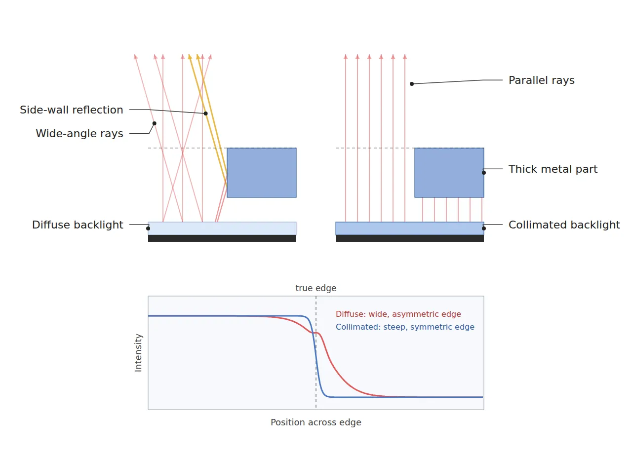
The wide profile in the figure stays even after a lens change, because the band remains as long as tilted light enters the cone the lens accepts. To my eye, only a profile whose edge breaks off within 1 to 2 px makes the dimension read on it trustworthy.
A collimated backlight narrows spread below acceptance
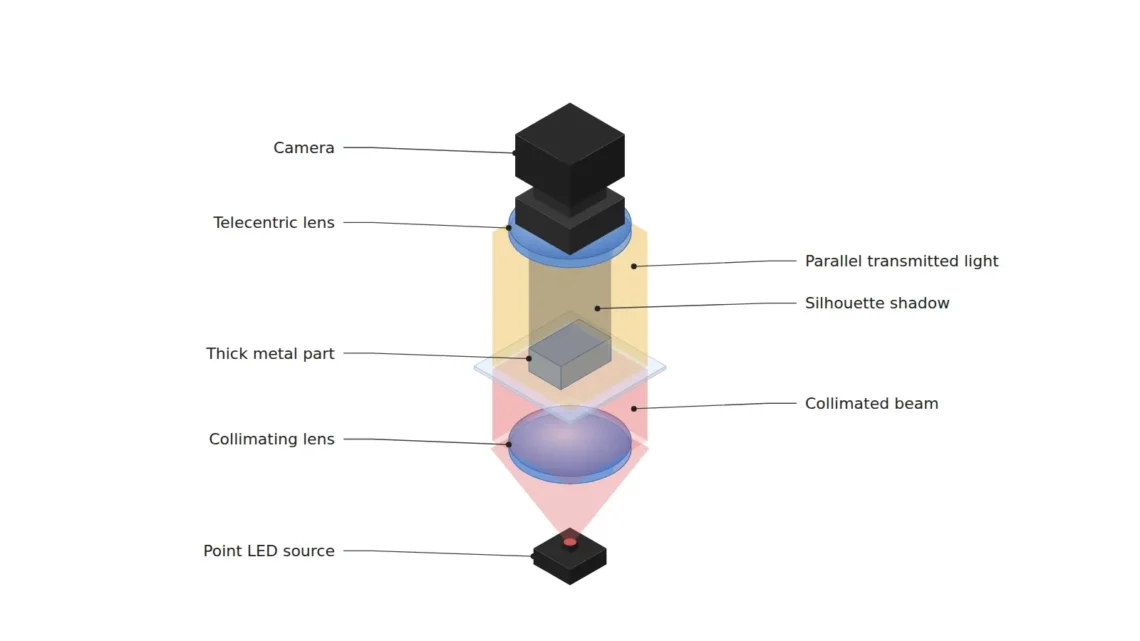
A collimated backlight4 places a small emitting area at the focus of a collimator lens and aligns the light parallel to the optical axis. The remaining half-angle of spread, the divergence5, is estimated as emitter diameter ÷ (2 × collimator focal length). With the tilt of the light reduced, the band width calculated above, thickness × tan(tilt), shrinks just as much.
Put a 1 mm emitter LED behind a collimator with a 100 mm focal length and the divergence is 0.5 ÷ 100 = 5 mrad, 0.29°. On the same 3 mm part the band narrows to 3 mm × 0.005 = 15 μm, 1.5 px, a fifth of the diffuse backlight. Swap in a 3 mm emitter LED for brightness and the divergence triples to 0.86°, widening the band again to 45 μm, 4.6 px.
7.6px
Edge blur of a 3 mm part on a diffuse backlight
1.5px
Blur with a collimated backlight of 0.29° divergence
1.15°
Tilt tolerance before backlight brightness drops
On a collimated backlight spec, the numbers I look at first are the emitter diameter and the collimator focal length, ahead of brightness. Those two give the divergence, and the ratio of divergence to lens acceptance angle sets edge quality and installation margin at once. If brightness falls short, lengthening the exposure or considering strobe drive protects the edge better than enlarging the emitter.
Past a 1.15° tolerance the whole image dims
Collimated light is touchy about tilt. Subtract the 0.29° divergence from the 1.43° lens acceptance and 1.15° remains: the tolerance within which the backlight can tilt without losing brightness. Past 1.15°, part of the light cone leaves the cone of the lens and brightness starts to drop, and at 1.43 + 0.29 = 1.72° the two cones barely touch and almost no light gets in. With a 3 mm emitter LED the tolerance halves to 0.57°.
A telecentric lens receives light at every point of the field through a cone pointing the same way, so when the backlight tilts, the whole image dims evenly more than one side does. The Edmund Optics note likewise states that if a telecentric illuminator and lens are misaligned even by a degree, the light appears extremely dim and edge contrast drops. An ordinary lens differs. Points at the edge of the field view the lens at a slant, so collimated light cannot enter in that direction and the periphery darkens first.
So at installation I would slip shims of known thickness under the backlight, tilting it 0.5° at a time, and record the angle at which brightness at the center and the four corners starts to fall together. If it differs widely from the calculated 1.15°, the focus position of the collimator or the telecentricity of the lens becomes the suspect. That record becomes the reference point later when the equipment moves or the backlight is replaced.
Sub-pixel edges stand only on the profile the light makes
A sub-pixel edge6 is found by interpolating, between pixels, the point of steepest brightness slope or the point at 50% between background and part brightness. This calculation rests on the premise that the profile is a narrow step, the same on both sides. When the band is wider than 7 px and lopsided, the slope maximum moves with side-wall reflectance and the 50% point wanders with background brightness.
Repeatability and accuracy differ. In that case repeatability can look fine while a difference from the true value, a systematic error, remains. Even if thirty placements of the same part gather within 1 μm, in a lot with different side-wall reflectance the place where they gather moves. Image processing alone cannot turn this lopsidedness back into the original step. Only after the collimated light narrows the band to 1.5 px does it make sense to take the slope with a Gaussian derivative of σ = 1.0 px and fit a parabola to the three points around the maximum, and averaging the per-row values over a 20 px wide caliper7 along the edge reduces random noise.
Wavelength matters too. The spot a lens draws cannot be smaller than its diffraction limit8, estimated on the object side as 0.61 × wavelength ÷ NA. At NA 0.025, 460 nm blue gives 11.2 μm (1.14 px) and 625 nm red 15.2 μm (1.55 px). Once collimated light has cut the geometric blur to 1.5 px, this diffraction blur remains at a comparable size, so for silhouette gauging like this I choose a blue source first.
From a 40 μm chip to 2 μm repeatability, one table
Moved into a spec, everything so far fits in one table: the size of the defects to catch, the backlight and lens, and the edge algorithm with its judgment criteria. The WD (working distance)9, the distance from the front of the lens to the part, is fixed by the design value of the telecentric lens, so the first step is checking whether the part-placing fixture and the backlight height fit within it.
| Item | Reference value | Condition and basis | In plain words |
|---|---|---|---|
| ① Minimum defect size · edge chip | 40 μm or more | 4.1 px at 9.86 μm/px. Design assumption | A bite about four pixels deep |
| ① Minimum defect size · burr | 30 μm or more | 3.0 px, at the edge of the detection floor. Design assumption | A barely visible bump |
| ① Minimum defect size · out of tolerance | 10 μm or more | 1.0 px, so judged by sub-pixel measurement in place of defect detection | Measuring a difference smaller than a pixel |
| ② Optical setup · lighting | Collimated backlight, 460 nm blue, 1 mm emitter, 100 mm collimator focal length | Divergence 0.29° (5 mrad), tilt tolerance 1.15° | Light lined up in one direction |
| ② Optical setup · lens and sensor | Object-side telecentric 0.35×, NA 0.025, 2,448 × 2,048 px, 9.86 μm/px | Acceptance 1.43°, diffraction limit 11.2 μm, field 24.1 × 20.2 mm. Design assumption | Looks straight down at every point |
| ② Optical setup · WD | WD of 110 mm or more secured (design assumption) | Based on the WD in the lens spec. Measure including fixture and backlight height | Fixture and light have to fit under the lens |
| ③ Algorithm parameters · edge | Gaussian derivative of σ = 1.0 px, parabola fit on the three points around the maximum | Assumes a 1.5 px band. Apply after confirming profile symmetry | Find the top of the slope between pixels |
| ③ Algorithm parameters · caliper | 20 px wide along the edge, per-row results averaged | Reduces random noise | Measure many rows and average |
| ③ Algorithm parameters · judgment | Repeat measurement 3σ ≤ 2 μm (0.2 px) | Design target confirmed by placing the same part 30 times | The same value after thirty placements |
Read the first two lines of the table together with the lighting line and the need for collimated light shows. At 9.86 μm/px a 40 μm chip is 4.1 px and a 30 μm burr 3.0 px, barely clearing the conditions for shape detection, while on a diffuse backlight the 7.6 px blur of a 3 mm part would be wider than the defects themselves. Only with collimated light cutting the blur to 1.5 px does a 30 μm burr separate from the edge blur, and the 0.2 px repeatability needed for a 10 μm tolerance becomes a realistic target.
Some targets do not suit collimated light. With almost no thickness, as with thin sheet or film, thickness × tan(tilt) is itself small and even a diffuse backlight keeps the blur around 1 px, so the diffuse option, easy to install and forgiving of tilt, is more economical. In a configuration with an ordinary lens and a large field, collimated light darkens the periphery, and a diffuse backlight that gives wide angles is the fit. For inspections that need to see the side wall itself, such as chamfers or burr height, collimated light deliberately erases side-wall information, so reflected lighting or a side view has to be added. The brightness spread inside the band changes widely with side-wall finish and gloss, so the real error difference between the two methods cannot be guaranteed before a sample test.
Calculating blur from divergence and acceptance angle is everyday work for a vision engineer who handles dimensional gauging, and one tangent and one division are enough to try it yourself. On the side buying the gauge, asking for the divergence of the backlight and the 3σ over thirty placements of the same part tells more precisely about real measuring ability than the lens magnification. This article explains technology and is not investment advice. See our Disclaimer.
Field Note
To gauge the silhouette of a metal pin on a backlight, I would not start with an offset that matches the caliper; I would pull the edge brightness profile row by row and look at the shape of the band. On a diffuse backlight the shape of the blur changes with side-wall gloss, so a lot change can even flip the direction of the error. Going collimated, the divergence of about 0.3° and the 1.15° tilt tolerance get calculated in advance, and the sub-pixel parameters come only after the profile is close to symmetric. When the material changes, the profile check comes first again.
Field Checkpoints
Once the edge profile and the tilt tolerance are confirmed, I check the whole gauge with the questions below.
- Is a WD of 110 mm or more secured by measurement from the lens front, including fixture and backlight height? (whether fixture and light all fit under the lens)
- Have the material, gloss and reflectance of the side wall been confirmed first? (side walls mixing sheared and fractured zones blur differently by spot)
- Is the backlight divergence well below the lens acceptance angle? (calculated from emitter diameter and collimator focal length and written in the spec)
- Is the backlight tilt within the tolerance (acceptance − divergence)? (checked by brightness at the center and four corners)
- Has the edge brightness profile been plotted to confirm symmetry? (sub-pixel parameters come after that)
- Is the repeatability over 30 placements of the same part (3σ) measured again when the lot changes? (whether the error has moved)
Glossary
- [1] Sheared and fractured zones sheared and fractured zones
On a press-cut face, the part the blade pushes smooth and shiny and the part where the material tears rough. Their reflectance differs, so brightness changes with height on the side wall. ↩ - [2] Telecentric lens telecentric lens
A lens that views every point in the field from a direction parallel to the optical axis. The size barely changes when the part moves slightly back and forth, so it is used for gauging. ↩ - [3] Acceptance angle acceptance angle
The half-angle of the cone of light a lens accepts from one point. With an NA of 0.025 it is 1.43°. ↩ - [4] Collimated backlight collimated backlight
A backlight that puts a small source at the focus of a lens and sends the light out in one orderly direction. It is touchy about installation tilt but makes edges stand sharp. ↩ - [5] Divergence divergence half-angle
Half the angle by which collimated light still spreads instead of staying perfectly parallel. It grows with a larger source and a shorter collimator focal length. ↩ - [6] Sub-pixel edge sub-pixel edge detection
A calculation that reads an edge position finer than one pixel from the shape of the brightness profile. It reads close to the true value only when the profile is narrow and symmetric. ↩ - [7] Caliper caliper tool
A measuring tool that cuts a narrow strip across an edge into many rows, finds the edge in each row and averages them. More rows mean less random noise. ↩ - [8] Diffraction limit diffraction limit
The limit below which the spot a lens draws cannot shrink, because light is a wave. The shorter the wavelength, the smaller the spot. ↩ - [9] WD working distance
The distance from the front of the lens to the surface being inspected. A telecentric lens has this distance fixed by design, so the fixtures must fit it. ↩
References
- Edmund Optics Knowledge Center, Silhouetting Illumination in Machine Vision (edge scattering from divergent light and how it stands out on metallic objects, why telecentric illuminators match the NA of a telecentric lens better, and the alignment sensitivity that dims the light at even a degree off)
- Edmund Optics Knowledge Center, Telecentric Illumination (high-contrast silhouettes from light parallel to the optical axis, compared with the blurred edges of a standard backlight)
- Edmund Optics Knowledge Center, The Airy Disk and Diffraction Limit (Airy disk diameter ≈ 2.44 × wavelength × f-number)
- Formulas: acceptance angle = asin(NA), blur bound = thickness × tan θ, divergence ≈ emitter diameter ÷ (2 × collimator focal length), tilt tolerance = acceptance − divergence, cut-off angle = acceptance + divergence, diffraction radius ≈ 0.61 × wavelength ÷ NA (half the Airy disk diameter 2.44 × wavelength × f-number, with NA ≈ 1 ÷ (2 × f-number)), pixel resolution = pixel size ÷ magnification
Related reading — Coaxial Light Alone Does Not Settle Fine Scratches on Polished Metal · Moving Parts Are Frozen by How Long the Light Stays On · When Height Varies, F7.1 Beats F16 on a Telecentric Lens

Noctvision
An engineer who has handled mechanical design and project management for production equipment since 2005. Here I work through the cameras, lenses and lighting that go into equipment with formulas and public data, and record the assumptions and sources alongside the numbers.


You May Also Like
In Automotive Part Appearance Inspection, Lighting Design Comes First
How Strongly Cross-Polarization Suppresses Glare Depends on the Lighting Angle