A Depth Camera’s Error Grows with the Square of Distance
OPTICS
A depth camera’s wobble grows with the square of distance, so to see a 0.5 mm lift it has to come within 21 cm.
The percentage on a spec sheet is one point on that curve. First work out where the gap between the two lenses and the part surface draw it.
About 14 min read
The first number that catches the eye on a depth camera spec sheet is a percentage. On September 24, e-con Systems introduced NetraVis, an active stereo1 depth camera it will unveil at VISION 2026 in October, and put a depth deviation of 1% or less up front; two days earlier, Cognex announced that it would acquire the depth camera company RealSense for $500 million. Now that a company that has built inspection equipment has agreed to take in depth cameras, it is time to work out how far the same camera sees when it sits above a board inspection station.
A board carries several surfaces in one frame. Slightly glossy green solder resist, a mirror-like metal shield can and a black connector body that sends little light back sit side by side. If one of those connectors is lifted by 0.5 mm, can this camera, mounted 40 cm above, pick out that lift? Mount it without the calculation and the lifted connector goes into the pass box, while the holes punched into the shiny can send good boards to the re-inspection shelf.
Before reading the percentage, I would write down two numbers: the distance from the camera to the board, and the gap between the two lenses inside the camera. Add what the part surfaces are like, and a few taps on a calculator show whether that camera can separate 0.5 mm.
The gap between two lenses is the ruler for distance
An active stereo depth camera holds two infrared cameras side by side, and the gap between them is called the baseline2. Because the two cameras see the same point from slightly different places, a point lands a few pixels apart horizontally in the left and right images. That shift is the disparity3, and depth is the focal length times the baseline divided by the disparity. Hold up one finger at arm’s length and close each eye in turn, and the finger jumps sideways against the wall behind it. Pull the finger toward your face and the jump grows.
Among film cameras, the rangefinder type looks at the subject through two windows set apart on the front of the body and measures distance by the angle at which the two images line up. A longer gap between the windows is known to allow more precise focusing, and in a depth camera that gap is the baseline. Both devices measure distance with a single triangle, and the longer its base, the larger the angle difference that the same change in distance produces.
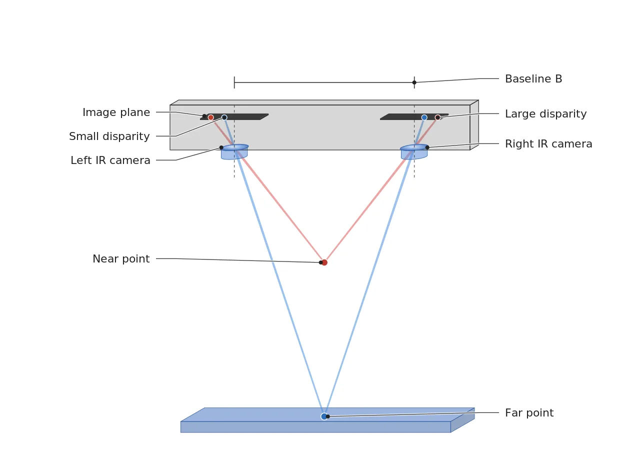
In the figure, the near point shifts a lot between the two images and the far point only a little. Because depth is inversely proportional to disparity, one pixel of disparity covers a wider stretch of depth the farther you go. In this figure my eye goes first to the angle at which the two sight lines meet. The narrower that angle, the longer the distance difference that one pixel of shift stands for.
From 0.6 mm at 40 cm to 0.17 mm at 21 cm
That inverse relation makes the error grow with the square of distance. Call the amount by which depth values rise and fall around a flat plate the wobble. The RealSense tuning guide calculates this wobble as distance squared × subpixel precision ÷ (focal length in pixels × baseline). Subpixel precision (subpixel RMS)4 is how finely the two images are matched below one pixel, written in pixels. Put 848 px across, a 90° horizontal field of view, a 50 mm baseline and a subpixel value of 0.08 into it, and the wobble at 40 cm comes out at 0.60 mm. All four are calculation assumptions borrowed from the example values in that guide.
To judge a lift, the wobble has to be much smaller than the lift. I call a height difference a lift only when it is at least three times the wobble. For a 0.5 mm lift, the wobble must be 167 μm5 or less, and solving the same formula backwards, the wobble drops under that line within 210 mm above the board.
0.60mm
Wobble at 40 cm with a 50 mm baseline
167μm
One third of a 0.5 mm lift
210mm
Farthest distance that keeps that wobble
Put the three numbers side by side and the gap between 40 cm and 21 cm shows. The distance was cut by not quite half, yet the wobble falls from 0.60 mm to 0.17 mm, below a third. Halve the distance exactly and the wobble becomes a quarter. A single percentage cannot hold this curve, so when you read a percentage on a spec sheet, I recommend first checking at what distance it was measured, and whether it describes how far the average sits from the true value or how much one frame ripples. The RealSense documents also measure these two separately, as Z-accuracy and RMS error.
Dots that vanish on a shiny can
The calculation above stands on a subpixel value of 0.08, and that value is set by the part surface. For the two cameras to find the same point, the surface needs a pattern. On a blank white wall there is no clue as to which point in the right image pairs with a point in the left, so these cameras spray an infrared dot pattern to draw one onto the surface. The RealSense testing document also names texture-less surfaces as a weak spot of stereo and says the projector fills that gap. Like the Intel stereo depth camera patent that adjusts the focus of the projection lens to keep the dots sharp (US 10,007,994 B2), the work of refining this dot pattern has built up over years.
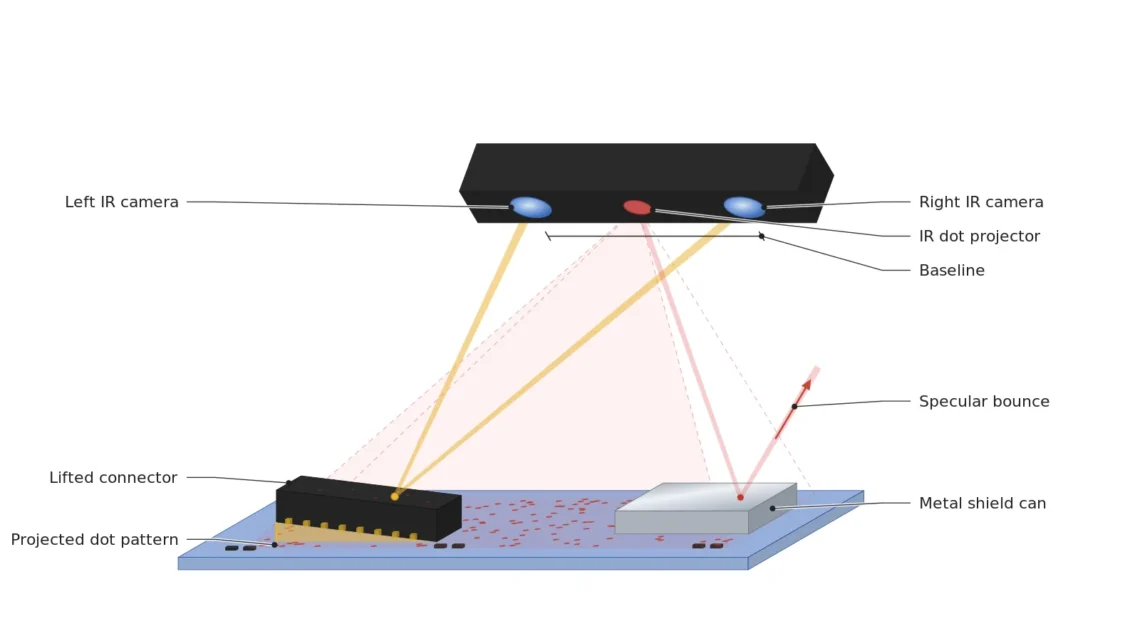
On a matte flat plate printed with a dot pattern, the RealSense guide says subpixel values drop below 0.1, and as low as 0.05 in good cases. The surfaces on a board differ from that plate. Green solder resist mostly returns the dots, but on glossy patches they flare and bunch to one side, and some black resins send back almost no infrared, so the dots on them turn faint.
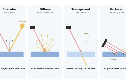
The hardest is the metal shield can. Shine a flashlight at a new coin at a slant and, instead of leaving a patch of light on the coin, the glint bounces off to one side and marks a small spot on the ceiling. An infrared dot landing on the shiny top of the can also bounces in a single direction by specular reflection6, and if no camera sits in that direction the dot disappears from the image. A pixel that finds no partner becomes a hole with a depth value of 0, and the share of pixels that do have values within the judgment area is called the fill rate7. So the guess that simply keeping the dots on will fill these holes does not last long.
The keep-it-on guess
Keep the infrared dots on, and any surface gets a pattern.
If it gets twice as bad
On shiny surfaces the dots bounce away. If matching gets just twice as bad, the distance needed to separate 0.5 mm shrinks from 210 mm to 149 mm.
The 149 mm on the card comes from solving the same formula again with the subpixel value changed from 0.08 to 0.16. What subpixel value a can or glossy solder resist actually gives cannot be guaranteed before a sample test. Until that number is measured, I would keep the can top out of the judgment area. And 149 mm runs into another wall as well.
A longer baseline keeps the camera from coming close
That wall is the minimum distance (MinZ)8. The stereo chip searches for disparity only within a fixed range, and the RealSense guide sets that range at 126 px and calculates the minimum distance as focal length in pixels × baseline ÷ 126. For the camera above that is 168 mm, and the guide itself gives about 16.8 cm for the D435 at 848 × 480. To separate the lift the camera must be inside 210 mm, and to get depth at all it must be outside 168 mm, so the place it can sit is a band of a little over 4 cm.
Does a longer baseline widen that band? The D455 product brief says that spreading the two lenses to 95 mm brought the depth error below 2% at 4 m. Calculated with the same sensor and lens and only the baseline stretched to 95 mm, the wobble at 40 cm falls to 0.32 mm, close to half. In exchange the minimum distance retreats to 320 mm, and the wobble at that closest position is still 0.20 mm, so it never reaches the 167 μm line.
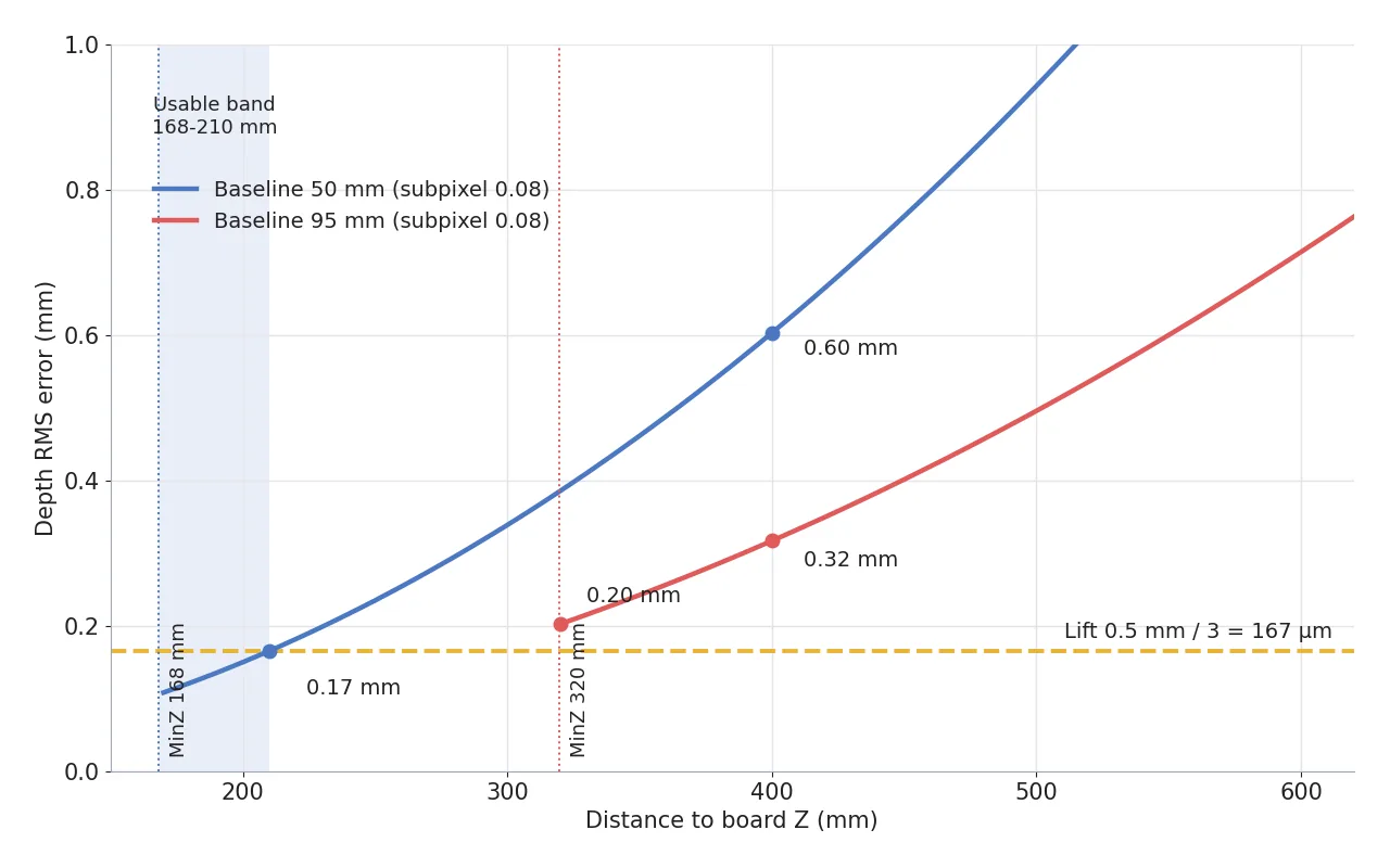
In the graph, the blue line starts at 168 mm and stays under the yellow line up to 210 mm, while the red line is already above the yellow line where it starts at 320 mm. With the disparity search range left at its default, this means the shorter baseline reaches the smaller wobble in inspection that works up close. For work that looks wide from far away the picture is reversed: beyond 32 cm the 95 mm baseline cuts the wobble at the same distance nearly in half, and for a fixed camera looking down at a table, a disparity shift9 can move the search range closer and bring the long baseline in.
A longer baseline costs one more thing. Beside a tall part a band appears that only one camera can see, and this occlusion10 area has no partner, so it stays as a hole. Its width is roughly baseline × part height ÷ (distance − part height); next to a 10 mm tall part it is 2.5 mm for a 50 mm baseline at 210 mm and 2.4 mm for a 95 mm baseline at 40 cm. If you take the board beside the part as the reference for measuring a lift, that reference can land inside this hole, so in my judgment it is safer to keep the reference area that far away from the part.
An inspection station with the camera inside 21 cm
Carried over to an inspection station, the calculation hangs the camera somewhere between 190 and 210 mm above the board and lets the judgment happen only where there are few holes. The table below writes the smallest lift, the camera position and the judgment rule one line each.
| Item | Value | Condition and basis | In plain words |
|---|---|---|---|
| ① Minimum defect size | Lift of a connector or shield can, 500 μm | Judge only when the wobble (RMS) is 167 μm or less (lift ≥ wobble × 3, Noctvision’s rule) | A 0.5 mm lift must be at least three times the wobble |
| ② Optical setup | 50 mm baseline active stereo, 848 × 480, 90° horizontal field of view, dot projector on, matte plate under the board, WD11 190 to 210 mm (whether it is secured: check on a sample that it is beyond the 168 mm minimum distance and that the lens focuses there) | Wobble 166 μm at 210 mm, occlusion band 2.5 mm beside a 10 mm tall part (subpixel 0.08 px assumed) | Keep the camera beyond 17 cm and inside 21 cm above the board |
| ③ Algorithm parameters | Subpixel 0.08 px or less on a patterned test plate; judgment value = mean of the part-top area − mean of the reference board area; reference area at least 2.5 mm from the part; hold the judgment when the area fill rate is below the limit; high-accuracy depth setting and temporal averaging | Subpixel below 0.1 on a well-patterned plate; the high-accuracy setting keeps only high-confidence depth, and temporal averaging reduces the wobble that changes frame to frame (RealSense tuning guide) | Compare only pixels you can trust, and put off the judgment on days with many holes |
The tightest cell in this table is the distance in the second row. A band of 190 to 210 mm is easy to drift out of from a sagging stand or a warped board alone, and the RealSense guide notes that these cameras are focused from 50 cm to infinity and start to go out of focus well below 20 cm. By my standard, saying this setup separates 0.5 mm takes numbers for subpixel and fill rate measured on real board samples.
The shape of the setup also comes from these limits. The camera is fixed firmly to a stand above the board, a matte plate that returns the dots well is laid under the board, and an edge PC next to the camera makes the call.
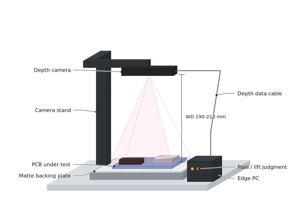
In the figure the stand height is set around a WD of 200 mm, and the matte plate also catches the dots that spill past the edge of the board. If the lift limit drops below 0.1 mm, or the shiny top of the can must be measured directly, an approach such as a 3D profiler that throws a laser line at a slant may do better than this camera. Which one fits can only be said after imaging a sample of that surface.
Who reads the depth and who pays for it
Deciding how many centimeters above the board to hang a depth camera falls to the machine vision engineer who handles 3D vision. Everything from choosing the camera and placing it to measuring the wobble on a test plate and dividing the judgment areas belongs to that work. If you are just learning it, I recommend getting two things into your hands first: the one-line formula depth = focal length × baseline ÷ disparity, and how to measure the wobble by imaging a flat plate. Those two keep working even when the camera names change.
Seen from the side that pays for the equipment, this calculation adds a few new lines to the quote. On top of the price of one depth camera come the stand that holds the camera inside 21 cm, the matte plate, and a first sample test that measures subpixel and fill rate for each surface. In its acquisition announcement, Cognex estimated the robotic perception market at about $600 million today and about $1.6 billion by 2030. This article explains technology and is not investment advice. See our Disclaimer.
Field Note
Setting up this station for the first time, I would lay a dot-printed matte plate 200 mm below the camera in place of a board and measure the wobble first. If it comes out around 0.15 mm, the 0.08 subpixel assumption holds; if it goes past 0.3 mm, I suspect the calibration or the focus. Next I load a board with a shield can and count the fill rate of the judgment area around the can. Until those two numbers are in, I do not enter a lift threshold.
Field Checkpoints
Once the two numbers from the plate and the can stay close to the calculation, the next step is to settle where the camera will be fixed. Before tightening the stand, I check these five.
- Is a WD of 190 to 210 mm secured between the camera and the top of the board, and is it farther than the 168 mm minimum distance? (whether the camera is so close that depth drops out entirely)
- On the pattern-plate test, is the subpixel value within 0.08 px and the wobble at 200 mm around 0.15 mm? (whether the camera measures as calmly as calculated)
- For each judgment area, did you note whether the surface is matte board, a shiny can or black resin? (whether the dots come back or bounce away)
- Is the reference area at least 2.5 mm away from tall parts? (whether it avoids the shadow that only one camera sees)
- Did you measure the fill rate of the judgment areas on the first sample, and set the judgment to be held when it falls short? (whether a pass is never issued from an area full of holes)
Glossary
- [1] Active stereo active stereo depth sensing
A way of measuring depth with two infrared cameras and a dot projector. It sprays dots even onto a blank wall so the two cameras can find the same point. ↩ - [2] Baseline stereo baseline
The distance between the lens centers of the two cameras. It is the same reason wider-set eyes judge distant objects more easily. ↩ - [3] Disparity stereo disparity
The number of pixels by which the same point is shifted horizontally between the left and right images. It grows for nearer objects, and depth is inversely proportional to it. ↩ - [4] Subpixel precision subpixel RMS
How finely the two images are matched below one pixel, written in pixels. A value of 0.08 means matching to roughly a twelfth of a pixel. ↩ - [5] μm micrometre
A length of 1 mm divided by 1,000. 167 μm is about 1 mm cut into six. ↩ - [6] Specular reflection mirror reflection
Reflection in which light hitting a smooth surface bounces off in one direction at the same angle it arrived. If the bounced light does not head toward the camera, that spot is recorded as dark. ↩ - [7] Fill rate valid depth ratio
The share of pixels within a judgment area that have a depth value. Holes carry no value at all, so they are counted apart from the wobble. ↩ - [8] Minimum distance MinZ
The closest distance at which a stereo camera can produce depth. It is found as focal length in pixels × baseline ÷ disparity search range. ↩ - [9] Disparity shift disparity offset
A setting that moves the disparity search range toward the near side to cut the minimum distance. In return, the farthest measurable distance shrinks too. ↩ - [10] Occlusion one-camera region
An area that one camera sees while the other has it hidden behind a part. With no partner to match, it remains as a band of missing depth. ↩ - [11] WD working distance
The distance from the front of the camera to the top of the object being inspected. In a depth camera, both the wobble and the minimum distance hang on this value. ↩
References
- Cognex, Cognex to Acquire RealSense, Expanding Machine Vision Leadership into High-Growth Robotic Perception Market, September 22, 2026
- RoboticsTomorrow, e-con Systems to Unveil New High-Accuracy 3D Depth Camera and Advanced AI-Powered Imaging Solutions at VISION 2026, September 24, 2026
- A. Grunnet-Jepsen, J. N. Sweetser, J. Woodfill, Best-Known-Methods for Tuning Intel RealSense D400 Depth Cameras for Best Performance, Rev 1.9
- Intel, Intel RealSense Camera Depth Testing Methodology, Rev 1.0, January 2018
- Intel, Intel RealSense Depth Camera D455 Product Brief
- Camera-wiki.org, Rangefinder base
- Patent US 10,007,994 B2, Intel Corp, Stereodepth camera using VCSEL projector with controlled projection lens
- Patent US 8,390,821 B2, PrimeSense Ltd, Three-dimensional sensing using speckle patterns
- Formulas: depth Z = f × B ÷ d, wobble (RMS) = Z² × subpixel ÷ (f × B), f = ½ × horizontal pixels ÷ tan(horizontal field of view ÷ 2), MinZ = f × B ÷ 126, occlusion band width ≈ B × h ÷ (Z − h)

Noctvision
A machine vision engineer who fits cameras, lenses, lighting, and image-processing algorithms together for a living. Years spent on continuous production lines, vibration, heat, and dust included, working through diffuse reflection, contrast, and resolution differences too fine for a spec sheet to capture inform every post here, closing the gap between theory and the shop floor. Off duty, that same eye for light and lenses goes into repairing fully mechanical vintage film cameras.

You May Also Like
Specular Reflection Erases Defects: How Cross-Polarization Catches Missed Detections on Highly Reflective Surfaces
Why Does Yesterday’s Threshold Miss Today? — Managing LED Light Output Degradation and Temperature Drift