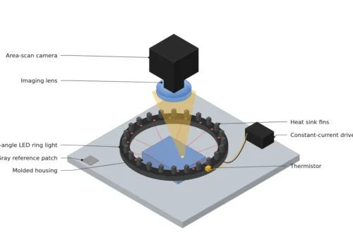
On Moving Parts, Photometric Stereo Shrinks the Standstill Condition to 0.5 ms
LIGHTING
Photometric stereo can capture normals on a moving part, but the standstill condition does not vanish; it moves into the 0.5 ms between two exposures.
Using a 300 μm dent in a matte-painted molded housing as the example, I calculated the exposure interval, Bayer resolution and lighting angle of color-multiplexed strobing.
About 15 min read
Light a sheet of paper on a desk from above with a lamp and the creases barely show; lay the lamp down to one side and every crease turns bright on one side and dark on the other. A shallow dent in a matte-painted molded housing behaves the same way. Its color and brightness are nearly the same as the good surface and only its tilt differs, so a 2D image under one lighting direction shows almost no contrast.
Photometric stereo1 moves that lamp to several directions while shooting the same spot, and solves for the surface normal2 from how each pixel’s brightness changes. Its old weakness was that the camera and the part both had to stay still throughout. The choices were to stop the line, to tie it to stop-and-go robotic inspection, or to downgrade surface inspection to sampling.
Color multiplexing, which divides lighting directions by color in place of time, goes after this weakness. What I want to work out is how the exposure interval, the pixels and the lighting angle must each be set to capture normals while the part moves, and what dividing by color costs. The part is taken as a matte-painted molded housing; highly reflective metal surfaces are handled separately.
A defect that differs only in tilt does not show under one light
The equations of photometric stereo rest on the assumption that the surface is close to Lambertian3. Such a surface looks equally bright from every direction, and its brightness is proportional only to the cosine of the angle between the lighting direction and the normal. A matte painted surface is close to this assumption, and surfaces with strong specular reflection4, such as a mirror-polished metal cover, sit farthest from it. In pixels where a specular highlight blows out white, the normal solution converges to a wrong value, so for such surfaces deflectometry, which reads the slope of a reflected pattern, is physically the right fit.
The size of the signal can be calculated too. Model a dent 300 μm across and 5 μm deep with a cosine cross-section and the steepest slope is 52 mrad, about 3°. On a Lambertian surface with the lighting tilted θ from the optical axis, brightness changes by slope × tan θ: 3.0 % at θ = 30°, 5.2 % at 45° and 9.1 % at 60°. That is a threefold difference. Laying the lights down makes the same dent stand out more, but on curved surfaces it also adds places that fall into shadow. Between the two, I start from around 45°.
Three or more directions are needed to solve the three components of the normal at each pixel. Divide the directions by time and you need one exposure per direction, and every exposure must hold the same surface point in the same pixel. That is exactly where the standstill condition comes from. How close a given matte paint really is to Lambertian varies with the paint and its gloss level and cannot be guaranteed before a sample test.
Dividing directions by time makes the part stand still
If the part moves while four frames are shot with the lights switched on one at a time, each frame puts a different surface point in the same pixel, and the normal calculation collapses by mixing brightness from different points. That is why sequential-lighting photometric stereo has stayed in laboratories, fixed installations and stop-and-go robotic inspection. Flashing the lights briefly by strobing5 reduces blur, but the movement between frames remains.
PHOTODEX from AIT (Austrian Institute of Technology), a system aimed at exactly this point, made the shortlist of five for the VISION Award 2026. According to the organizer’s shortlist description, it pairs high-speed imaging with bright, color-coded strobing illumination to get the needed lighting information from two closely spaced exposures, and it inspects while held in the hand or carried by a continuously moving robot. The description also says it estimates the camera pose against a known CAD model, registers every image to the digital twin and records each detected defect as a position on the model. The award announced on October 7, 2026 at VISION 2026 in Stuttgart went to photonicSENS for its light field camera, and PHOTODEX remained a finalist.
Two exposures should be read less as the registration problem disappearing than as the time to be registered shrinking to the gap between two exposures. How many micrometers the part moves within that gap becomes the new design specification, and that value is set by calculation. However short the strobe, the distance traveled between the two exposures stays.
The standstill condition moves into 0.5 ms between two exposures
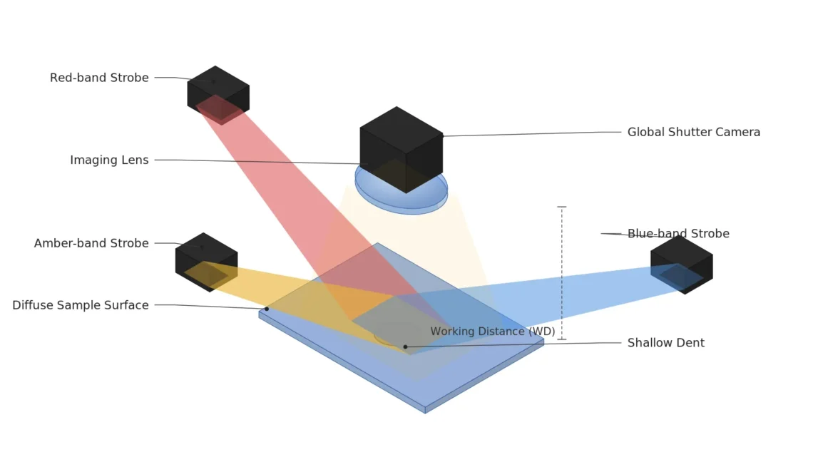
The calculation uses a color global shutter6 camera with 2,048 × 1,536 px and 3.45 μm pixels (assumed). At 50 μm/px the field of view is 102.4 × 76.8 mm, and making the 0.069 magnification with a 25 mm lens puts the WD7 at about 387 mm, leaving ample room for a multi-direction lighting ring. Between the two exposures the part must move less than one pixel, 50 μm, for the same pixel in both images to hold the same point.
Sweeping by hand at 100 mm per second, the two exposures must fall within 0.5 ms, the frame interval of a 2,000 frames-per-second camera. A robot moving at 250 mm per second cuts this to 0.2 ms, the 5,000 frames-per-second class. A 200 frames-per-second camera moves 500 μm, ten pixels, during its 5 ms interval, so the two images would have to be aligned by image registration, and a featureless matte painted surface offers few clues to align by. Registration is not easy. That is why high-speed imaging comes attached as a condition of this method.
Blur within a single exposure is set by the strobe width. A 100 μs strobe gives 10 μm, 0.2 pixels, at 100 mm per second, and still only 25 μm, half a pixel, at 250 mm per second. Packing the same light energy into 100 μs in place of 10 ms of continuous light takes 100 times the peak output, and the lighting power supply and heat design follow from that number.
0.5ms
Allowed gap between two exposures at 100 mm per second (one pixel = 50 μm)
100배
Peak output of a 100 μs strobe against 10 ms of continuous light
5.2%
Brightness change from a 3° dent under 45° lighting
The three numbers show that photometric stereo in motion has turned into a camera and lighting problem. High-speed capture takes over the registration that algorithms used to do, the strobe takes over the blur, and the lighting angle protects the 5 % of signal that remains. If even one of the three slips, the normal map blurs into something that still looks plausible.
Directions split by color share out the Bayer pixels
Dividing directions by color cuts the exposures but costs something elsewhere. The figure is a concept diagram of one color exposure splitting into color bands and becoming a normal map.
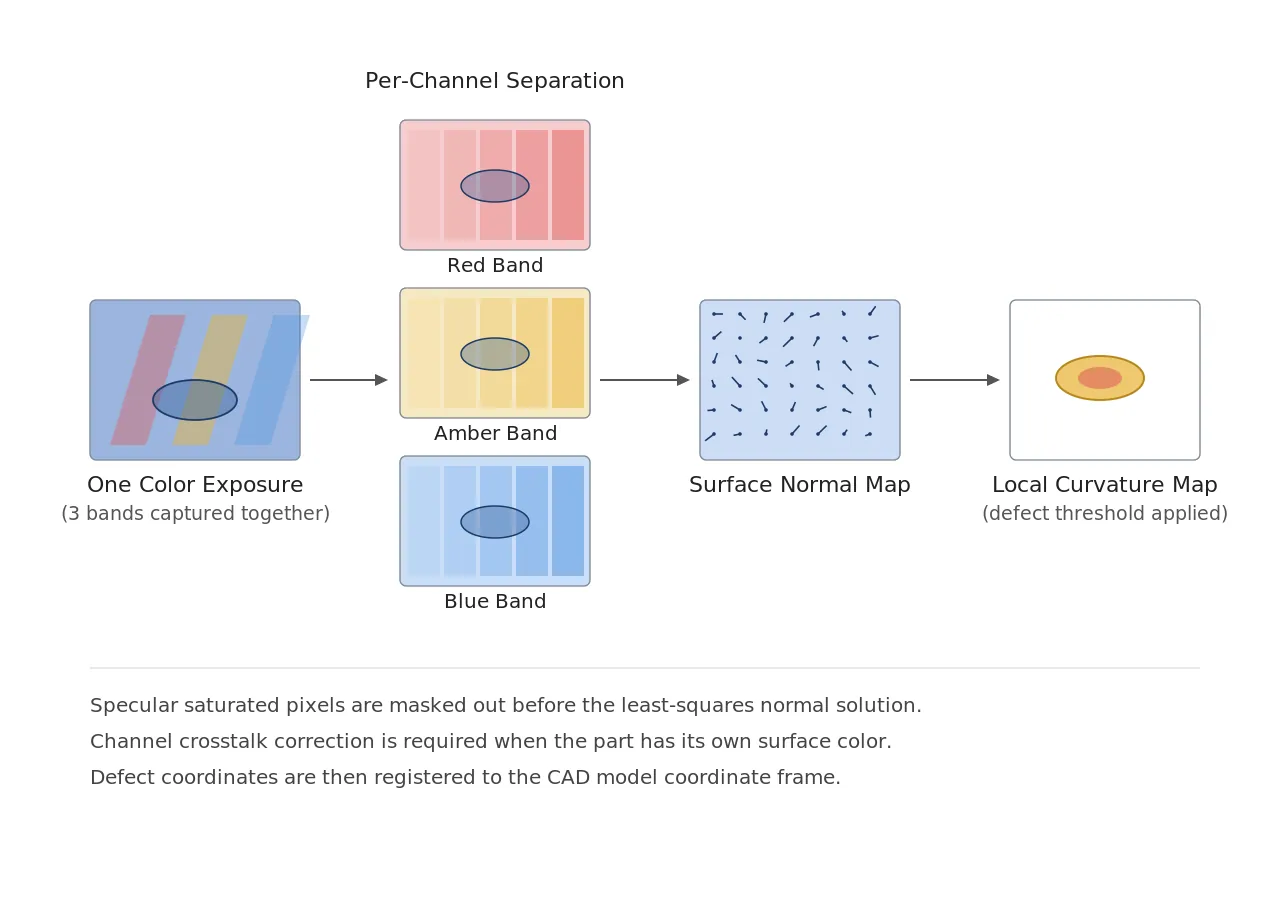
The Bayer pattern8 of a color camera takes red and blue on only one pixel in every two across and down. The direction assigned to the red light is sampled only every 100 μm, so a 300 μm dent spans 6 pixels but only 3 samples in that direction. An engraved character with a 150 μm stroke gets 1.5, too few to tell whether part of it is missing. There are too few samples. To see the engraving as well, the pixel has to shrink to 25 μm and the field of view to 51.2 × 38.4 mm, which puts the WD at about 206 mm with a 25 mm lens and cuts the interval between exposures again, to 0.25 ms at 100 mm per second.
When the part has its own color, one more problem attaches. On a red painted surface, the signal in the direction assigned to the blue light becomes much weaker than in the red one, enlarging the normal error in that direction, and the crosstalk9 in which color filters pass a little of each other’s wavelengths has to be measured on a white reference and subtracted. So before choosing color multiplexing, I set the part color side by side with the table of lighting color assignments. For parts that come in many colors, dividing directions by time and accepting a standstill does better on accuracy.
Getting normals from one image already appears in a 2009 patent
The idea of dividing directions by color is not new in itself; what is new lies in motion and coordinates. The patents in the table below show how the idea of getting normals from one or a few images and the method of building inspection images from normals have developed.
| Patent | Title | Assignee (original) | Priority · granted |
|---|---|---|---|
| US 8,717,578 B2 | Profilometer, measuring apparatus, and observing apparatus | Omron Corp. | 2009-04-10 · 2014-05-06 |
| US 2012/0056994 A1 | Single-shot photometric stereo by spectral multiplexing | University of Southern California | 2010-08-30 · abandoned without grant |
| US 9,396,544 B2 | Single image photometric stereo for colored objects | Adobe Inc. (Adobe Systems Inc.) | 2014-01-08 · 2016-07-19 |
| US 9,773,304 B2 | Inspection apparatus, inspection method, and program | Keyence Corp. | 2014-06-09 · 2017-09-26 |
The Omron patent uses a light source distribution whose brightness varies with angle, and in its embodiments it estimates normal directions from a single image with RGB color-coded lighting. The University of Southern California application treats surface color as a variable and solves color and normals together from one image with three or more light sources and a camera with five or more channels; it was abandoned without being granted. The Adobe patent splits a single image taken under red, green and blue lights into channels to find the normals and depth of colored objects. The Keyence patent builds an inclination image from normals obtained from images under three or more directions and combines it with reduced images to produce inspection images matched to defect size. That two of these filings deal with the part’s own color backs up the need to review color assignments.
What comes new with inspection in motion is coordinates. At a fixed station the part always arrives at the same place, so position in the field of view is position on the part, but when the camera moves by hand or by robot the viewpoint differs from shot to shot, and where a defect sits on the part has to be fixed separately. Process improvement needs defect history to accumulate at the same spot on the same part, so I find the value of inspection in motion in this coordinate system more than in its speed. I read PHOTODEX’s emphasis on registration to the CAD model and the digital twin10 as coming from the same place.
Setup table for a normal map shot in motion
Gathering the calculations into one table shows that photometric stereo on a moving part ties pixels, time and lighting angle into a single equation. At the center of the table is the relation that narrowing the field of view narrows the allowed interval with it.
| Item | Value | Condition · basis | In plain words |
|---|---|---|---|
| ① Minimum defect size (μm) | Dent 300 μm across · 5 μm deep, sink mark 500 μm across, engraved stroke 150 μm wide | Dent on 6 pixels at 50 μm/px (3 red · blue samples). Engraving needs 25 μm/px for 3 color samples | Splitting by color halves the pixels per direction |
| ② Lighting | Color-assigned strobing per direction (red · amber · blue), about 45° from the optical axis, 100 μs strobe | Brightness change of 5.2 % from a 3° dent (45°). Peak 100 times that of 10 ms continuous light. Part color checked against the assignment table | Flash short and bright |
| ② Camera · lens · WD | Color global shutter 2,048 × 1,536 px (3.45 μm assumed), 25 mm F/5.6, field of view 102.4 × 76.8 mm | WD of about 387 mm must be secured (thin-lens approximation), exposure gap 0.5 ms (100 mm per second) · 0.2 ms (250 mm per second) | Not even one pixel of movement between the two shots |
| ③ Algorithm parameters | Crosstalk matrix correction → Lambertian least-squares normals → curvature11 map, masking of saturated specular pixels | Threshold of 3σ in curvature deviation (re-estimated from 30 good parts), defect coordinates converted to the CAD frame | Judge by bending more than by brightness |
The cell in this table that drags all the others along is the exposure gap in ②. Shrinking the pixel to 25 μm to see the engraving narrows the gap to 0.25 ms and calls for a faster camera and a brighter strobe in proportion. Resolution, travel speed and lighting peak output are bound in one equation, so the specification has to write all three on the same line. The three move as one.
Some parts are better served by another method. High-gloss or mirror-like surfaces break the Lambertian assumption, so deflectometry fits, and strongly and variously colored parts are measured more accurately by dividing directions by time and accepting a standstill. If the defect already shows as a color or brightness difference, normal recovery only adds computation, and if absolute height is needed, structured light or confocal methods do better because of the low-frequency error that builds up when slope is integrated. Surface reflection properties change with the paint lot, surface treatment and aging, so which way fits cannot be guaranteed before a sample test.
Building the optics is the vision engineer’s job, but the time cells of this table have to be set together with whoever chooses the camera and lighting power supply, and the coordinate cells with whoever accumulates quality data. When reviewing the spec, check how many milliseconds separate the two exposures and whether defects are kept as part coordinates, more than whether the system claims to inspect in motion. This article explains technology and is not investment advice. See our Disclaimer.
Field Note
In evaluating this method, I would multiply the exposure gap by the actual travel speed before writing down the claim that two exposures remove the standstill condition. If the result exceeds one pixel, 50 μm, I would suspect registration error ahead of the quality of the normal map. Next I would measure color-channel crosstalk on a white reference and check, for every lot where the part color changes, what fraction of the red signal the blue direction delivers.
Field Checkpoints
Once the travel distance and the crosstalk have been checked, it is time to answer the questions below.
- Is a WD of about 387 mm from lens to part (25 mm lens, 102.4 mm field of view) actually available, clear of the multi-direction lighting ring and the handle or robot end? (about 206 mm when the field is narrowed for engraving)
- Has it been confirmed on real parts that the surface is dominated by diffuse reflection? (normals go wrong where specular highlights blow out white)
- Is the exposure gap shorter than the time to move one pixel (50 μm) at the actual travel speed? (0.5 ms at 100 mm per second)
- Is the camera a global shutter that can take two exposures within that gap?
- Can the strobe handle the peak output and heat of 100 μs pulses? (100 times that of 10 ms continuous light)
- Does the part color clash with the lighting color assignment? (a blue direction on a red part gives a weak signal)
- Is there a path for converting defect coordinates into the CAD frame?
Frequently Asked Questions
How many lighting directions are right?
Three is the minimum for solving the three components of the normal, and four or more is safer against a specular highlight or a shadow ruining one direction. Carrying three colors in each of two exposures holds up to six directions, so three or more remain even after dropping a direction caught in a specular highlight. The ring grows with the number of directions, so its diameter has to be weighed within the 387 mm WD.
Can a normal map measure a depth of 5 μm?
Integrating the normals does give height, but slope noise accumulates along the integration and swells at low frequencies. Relative height over a narrow range, such as the depth of a single dent, is usable, while absolute height over a wide range, such as the warp of a whole part, is better measured with structured light or confocal methods. Making the decision on the curvature map, without converting to height, is the way to avoid this integration error.
Glossary
- [1] Photometric stereo photometric stereo
A method that shoots the same spot several times under changing lighting directions and solves the surface tilt from the brightness changes. It works like reading the creases in paper by moving a desk lamp around. ↩ - [2] Surface normal surface normal
The direction standing perpendicular to the surface at a point. How far the normal leans is the tilt of that point. ↩ - [3] Lambertian Lambertian surface
An ideal matte surface that looks equally bright from every direction. Its brightness is proportional to the cosine of the angle between the lighting and the normal. ↩ - [4] Specular reflection specular reflection
Reflection in which light bounces off in one direction at the same angle it arrived, as from a mirror. It is what blows highlights out white. ↩ - [5] Strobing strobing
Switching lighting on strongly for a very short time. The shorter it is on, the less a moving object blurs. ↩ - [6] Global shutter global shutter
A sensor mode in which every pixel starts and ends its exposure at the same instant. Unlike a rolling shutter, which has a time offset per row, it does not record moving objects slanted. ↩ - [7] WD working distance
The distance from the lens to the surface being inspected. The value in the text uses a thin-lens approximation measured from the lens center. ↩ - [8] Bayer pattern Bayer pattern
An arrangement that places one of red, green or blue filters on each pixel of a color sensor in a checkerboard. Looking at a single color, the pixel spacing widens. ↩ - [9] Crosstalk color crosstalk
Light from another color’s lighting leaking a little into one color channel. The leak ratios are measured on a white reference and removed with a matrix. ↩ - [10] Digital twin digital twin
A digital model with the same shape and coordinates as the real part. Recording defects as positions on this model lets history build up at the same spot. ↩ - [11] Curvature curvature
A value for how much a surface bends, the rate at which the tilt changes from place to place. It grows where the tilt changes quickly, as at the edge of a dent. ↩
References
- Messe Stuttgart, VISION Award 2026 Shortlist of the best submissions (AIT PHOTODEX: high-speed imaging with color-coded strobing, two closely spaced exposures, CAD-based pose estimation and registration to the digital twin; presentation session on October 7, 2026)
- Imaging and Machine Vision Europe, photonicSENS wins VISION Award 2026 for single-shot 3D light field camera technology (award presented October 7, 2026)
- Omron Corp., US patent US8717578B2, Profilometer, measuring apparatus, and observing apparatus (priority April 10, 2009; filed April 9, 2010; granted May 6, 2014)
- University of Southern California, US patent application US20120056994A1, Single-shot photometric stereo by spectral multiplexing (priority August 30, 2010; filed August 30, 2011; published March 8, 2012; abandoned)
- Adobe Inc. (original assignee Adobe Systems Inc.), US patent US9396544B2, Single image photometric stereo for colored objects (priority and filing January 8, 2014; granted July 19, 2016)
- Keyence Corp., US patent US9773304B2, Inspection apparatus, inspection method, and program (priority June 9, 2014; filed December 19, 2016; granted September 26, 2017)
- Formulas: peak slope of a cosine section = π × depth ÷ diameter, Lambertian brightness change ≈ slope × tan(lighting tilt), field of view = pixel count × pixel resolution, WD ≈ f × (1 + 1/m), allowed exposure gap = pixel resolution ÷ travel speed, blur during exposure = travel speed × strobe width, peak output ratio = continuous exposure time ÷ strobe width, Bayer color sample spacing = 2 × pixel resolution
Related reading — Brightness Augmentation Cannot Move Shadows or Highlights · Moving Parts Are Frozen by How Long the Light Stays On · What Optical Design Needs to Not Miss Defects on a High-Speed Line

Noctvision
An engineer who has handled mechanical design and project management for production equipment since 2005. Here I work through the cameras, lenses and lighting that go into equipment with formulas and public data, and record the assumptions and sources alongside the numbers.


You May Also Like
How to Handle Imaging on Highly Reflective Surfaces
In SWIR, One Stop Down Erases a 3.4 μm Pixel