A Blind Hole’s Floor Gets Only 2.7 % of a Dome Light
LIGHTING
The floor of a blind hole with aspect ratio 3 gets only 2.7 % of the light a dome gives the top surface, and the way to win that light back narrows to coaxial light running down the hole axis.
For a hole 5 mm wide and 15 mm deep, I calculated how much dome, ring and coaxial light reaches the floor, and how much of the floor camera angle and lens type hide.
About 15 min read
Say a 100 μm chip is left on the floor of a blind hole1 5 mm wide and 15 mm deep, cut with an end mill into an aluminium block. Under a dome light the top surface glows white while the inside of the hole shows up as a black circle, and the chip is buried in that circle. Run the numbers and this floor gets only 2.7 % of the light the dome gives the top, so getting light down there takes coaxial light arriving within 9.46° of the hole axis.
A paper on blind hole measurement published in Frontiers in Artificial Intelligence on October 26 approaches the same problem from the robot side. It measured 30 holes in an acrylic block, 5 to 15 mm in diameter, 10 to 45 mm deep, with depth-to-diameter ratios of 2.0 to 3.1, using a camera on a six-axis robot, and reported that the mean position error rose from 0.028 mm to 0.041 mm in trials at approach angles of 15° or more. The author notes that every trial at 15° or more used medium or high reflectivity surfaces, so the effects of angle and reflectivity could not be separated, and I welcome that caveat. Inside a hole, the angle at which light enters and the angle at which the camera looks in are bound by the same geometry, which makes them hard to pull apart.
First, the surface. An end-milled aluminium floor drags light along the tool marks as it scatters it, so specular reflection and diffuse reflection2 are mixed. A chip may flash brighter than the floor or sink darker, so the sign of the contrast3 cannot be fixed in advance, and the numbers below only go as far as whether enough light reaches the floor to pick out a chip. How much contrast such a mixed surface actually gives cannot be guaranteed before a sample test.
Light reaches a hole floor only from inside a cone set by width and depth
The arithmetic gets easier if you imagine standing at the center of the floor and looking up. The only sky you see is inside the round rim of the opening, and the half angle that rim makes at the floor center is atan(diameter ÷ (2 × depth)). For 5 mm wide and 15 mm deep it is 9.46°, and any light that falls straight onto the floor center must come from inside this cone. Light from outside the cone hits the wall first and reaches the floor only after one or two more bounces, weaker each time.
The width of that cone is set by the aspect ratio4 of the hole. A hole twice as deep as it is wide narrows it to 14.04°, three times to 9.46°, four times to 7.13°, and only a shallow groove half as deep as it is wide opens it to 45°. I would write this angle down before opening any lighting catalog. Whatever the light, recounting it as how much it puts inside this cone reduces the comparison to a single line.
Under a dome light, the floor of an aspect-ratio 3 hole gets 2.7 % of the top
A dome light5 is built so its whole inner hemisphere glows evenly, which pours light from every direction onto open places such as the top surface. The irradiance an evenly bright surface gives a point is proportional to the projected solid angle that surface fills, so the top, which sees the whole hemisphere, gets π, and the floor center, which sees only a cone of half angle α, gets π sin²α. Their ratio is sin²α, and 9.46° gives 0.027. Light bouncing in from the walls is left out, so the real floor gets brighter as wall reflectivity rises, and that share has to be measured on a sample.
In exposure terms 2.7 % is about 37 times, a little over five stops. Set the floor to mid gray on an 8-bit image and the top takes 37 times that and saturates early; set the top correctly and the floor becomes a black circle near zero. If the chip returns light only a few percent differently from the floor, that difference falls within a few levels near zero, where it is hard to tell from sensor noise. A dome also leaves a gap in its light where the camera hole sits, and the mark that dark spot leaves on smooth surfaces is covered in The Black Spot in the Middle of a Dome Light Is the Camera Hole. Repeat the same calculation over a range of aspect ratios and you get the graph below.
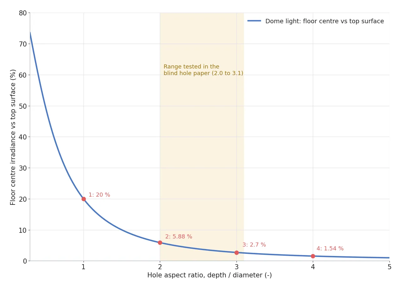
The first place to look on the graph is between aspect ratios 1 and 2. A hole as deep as it is wide gets 20 %, twice as deep drops it to 5.88 %, and at 3.1, the end of the paper's test range, it is 2.54 %. Past that the curve looks gentle, but only a few percent are left, so for holes beyond aspect ratio 2 any attempt to rescue the floor by turning the dome up burns the top first. That is the range where I put the dome down.
From 18.43° onward, oblique light never touches the floor
Light arriving at a slant, as from a ring light, fares worse. Parallel light tilted θ from the hole axis directly lights only 1 − aspect ratio × tan θ of the floor diameter, and the rest falls in the shadow of the wall. At aspect ratio 3 that leaves 73.8 % at 5° and 19.6 % at 15°, and it reaches zero at 18.43°. Lighting a chip from a low angle to draw out a long shadow works well on a flat top surface, but inside a hole the light never even gets down to the floor.
So the light for the floor has to run parallel to the hole axis, and in machine vision that job belongs to coaxial illumination6. A half-silvered mirror (beam splitter) in front of the lens turns sideways light downward along the same axis as the lens, so the light drops straight onto the floor without brushing the wall. Seen from the floor center, the light only has to come from inside the 9.46° cone, so if the spread of the coaxial light is narrower than that, the floor and the top get light of the same strength. How coaxial light misses the lens when a smooth surface tilts even slightly is calculated in Coaxial Light Alone Does Not Settle Fine Scratches on Polished Metal. Cut the hole lengthwise and draw the light paths of the two lights side by side, and the difference is plain at a glance.
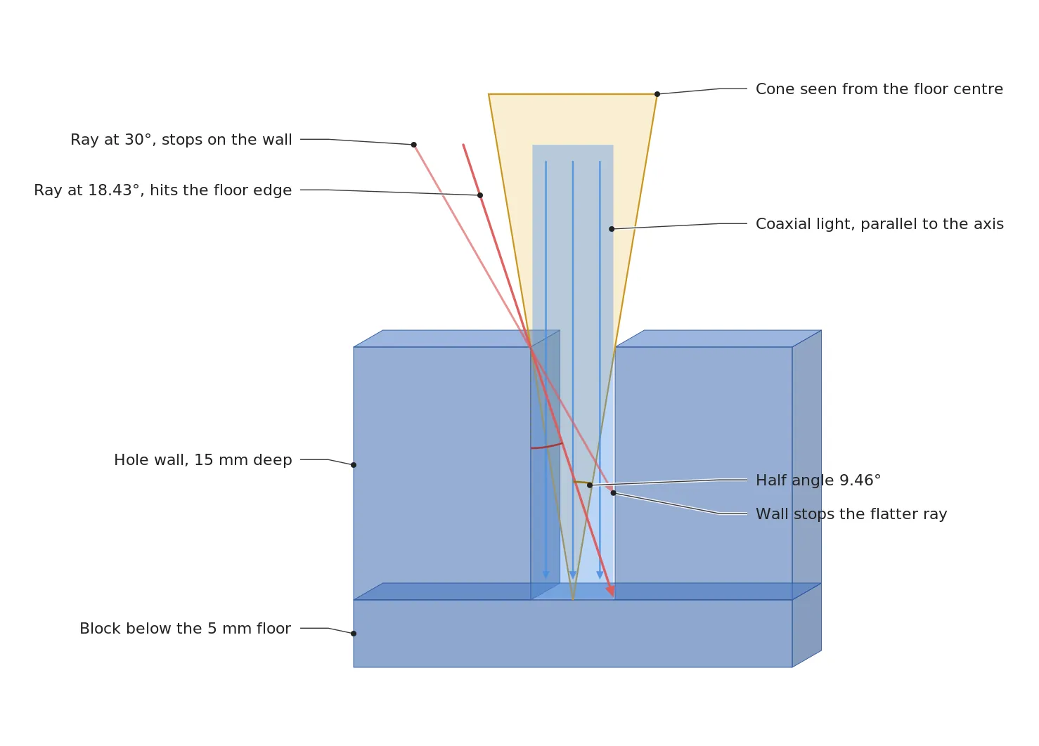
The red light on the left of the figure comes in at 18.43° and barely touches the edge of the floor, and the flatter 30° ray stops on the opposite wall. The yellow cone in the middle is the opening as seen from the floor center, and the blue coaxial light runs straight down inside it. The price is light. With a 50:50 beam splitter the source light loses half on reflection going down and half again on transmission coming back, so at most 25 % reaches the camera, but it shrinks the brightness gap between floor and top from 37 times to the difference in their reflectivity, so in front of a blind hole I accept that loss.
Tilt the camera 15° and 80 % of the floor hides behind the wall
The geometry of the path light takes in also applies to the path the camera looks along. When the camera axis tilts φ from the hole axis, only 1 − aspect ratio × tan φ of the floor diameter is visible, and at aspect ratio 3 and 15° just 19.6 % remains. At aspect ratio 2 it is 46.4 %, and at 3.1, the end of the paper's range, 16.9 %. This geometry points the same way as the paper's report of larger position error at 15° and above, but since the author states that the effect is mixed with reflectivity, I keep this calculation as the first suspect to check and do not treat it as proof of the cause.
Even with the camera upright, the same thing happens at the edge of the image. In an ordinary lens the chief rays7 spread outward away from the image center, so a hole at the edge is seen at a slant. Taking the entrance pupil as the lens front and assuming a horizontal FOV8 of 20 mm viewed from 110 mm in front of the lens, the chief ray angle 10 mm out at the edge is 5.19°, and an aspect-ratio 3 hole there shows only 72.7 % of its floor diameter. To see at least 90 % of the floor, the hole has to sit within 3.67 mm of the image center, and the chief rays leaning at a sensor corner in Why Do the Corners of a 100 MP Sensor Go Dark First? share the same root.
A telecentric lens9 removes that spread. Its object-side chief rays stay parallel to the axis across the field, so holes at the edge are also seen head-on, and a 2005 Vision Systems Design article lists looking down tube bores and checking hole clearance among the main uses of these lenses. The paper above also states that it used a low-distortion telecentric lens. In exchange, the front of the lens has to be larger than the field of view, which takes up that much space over the station, and where to set its aperture follows the same reasoning as When Height Varies, F7.1 Beats F16 on a Telecentric Lens. Plotting how much floor stays visible against tilt for each aspect ratio gives the following.
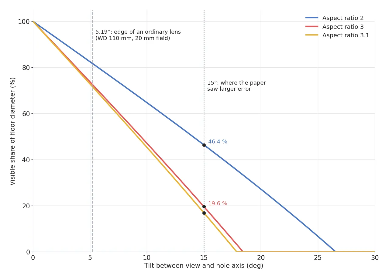
Where the three lines reach zero, at 26.57° for aspect ratio 2, 18.43° for 3 and 17.88° for 3.1, is the limit of tilt at which that hole's floor can be seen. The 5.19° at the edge of an ordinary lens is the dashed line at the left of the graph, yet on the aspect-ratio 3 line more than a quarter of the floor diameter is already cut away there.
The top rim and the floor are never sharp in the same frame
Once the floor is bright and seen head-on, focus is still left. Viewing 20 mm across with a 2,448 × 2,048 px sensor of 3.45 μm pixels gives a magnification of 0.4223×, each pixel covers 8.17 μm, a 100 μm chip spans 12.2 px, and resolution10 has room to spare. With the allowed blur set at 2 px (6.9 μm), the depth of field11 at F5.6 works out to 0.616 mm, and holding the floor 15 mm down and the top rim together would take F136. An aperture like that erases the chip itself through diffraction, so the rim and the floor are better shot as two frames with separate focus.
0.616mm
Depth of field at the floor, F5.6 and 0.4223× magnification
136F-number
Aperture needed to hold 15 mm of depth in one frame
24.2μm
F5.6 diffraction blur diameter, mapped to the object side
Diffraction already shows at F5.6. At an effective F-number of 7.96 the Airy disk is 10.2 μm across on the sensor, or 24.2 μm on the object side, which lays about 1.48 px of blur on each side of a chip outline. That is enough to size a 100 μm chip, but chasing debris under 50 μm means opening the aperture and narrowing the depth of field further, so I recommend first checking that the floor height varies by less than 0.616 mm. The half angle the lens accepts on the object side is 1.52°, far narrower than the 9.46° hole cone, so the hole wall never clips the lens's view.
A station that images only the floor with coaxial light and a telecentric lens
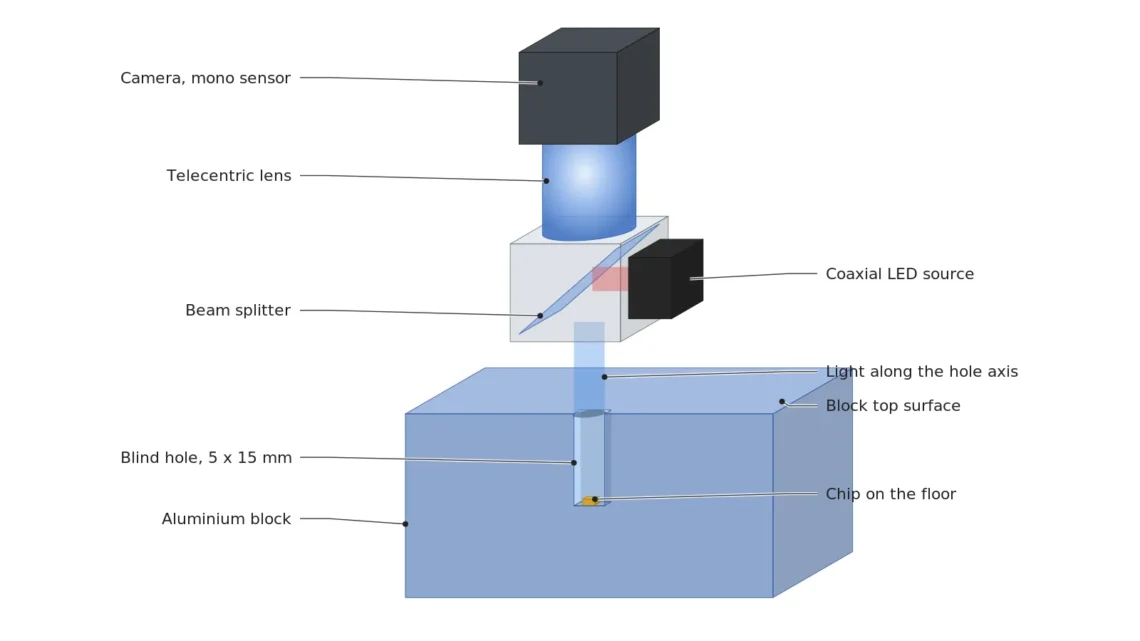
Tie these calculations into one station and the camera, telecentric lens and coaxial light stand in a single line over the hole axis. Only when the rim on top of the block needs its own look is a low-angle ring light added for a second frame.
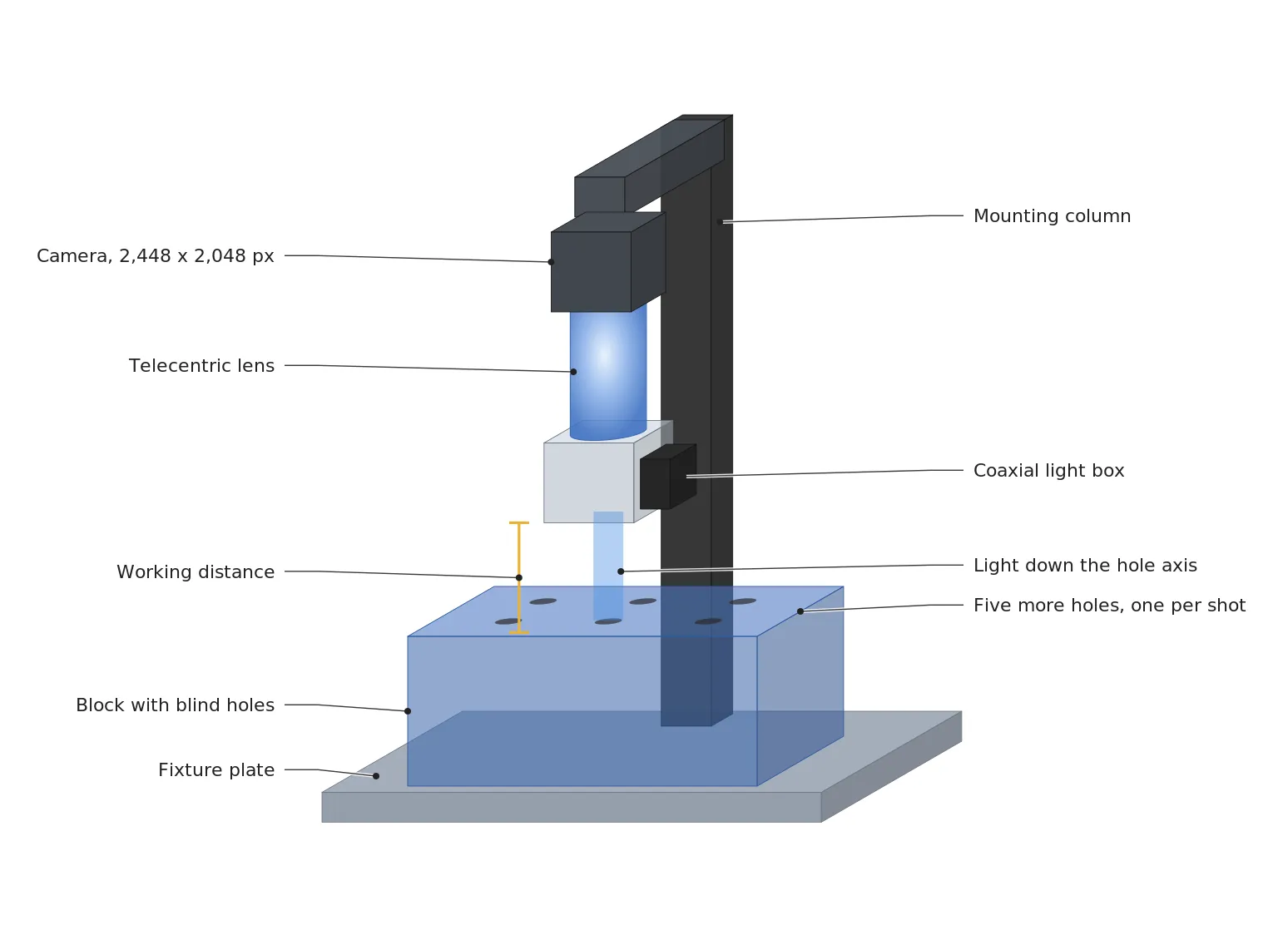
The place to look in the figure is the gap between the coaxial light box and the top of the block. The coaxial box sits in front of the lens, so its height has to fit inside the WD12, and the calculation above only assumed 110 mm in front of the lens, so the real distance must be checked again against the datasheet of the chosen lens. With several holes, split the shots so each hole sits at the image center, and if an ordinary lens is unavoidable, the 3.67 mm radius above sets how many holes fit in one frame. The values that run from chip size to algorithm go into the three rows below.
| Item | Value | Basis | In plain words |
|---|---|---|---|
| ① Minimum defect size | 100 μm (12.2 px) | 20 mm field ÷ 2,448 px = 8.17 μm/px | One chip covers a little over 12 pixels across |
| ② Optical setup | Coaxial light (spread within 9.46°), telecentric lens 0.4223× F5.6, 2,448 × 2,048 px 3.45 μm monochrome sensor, WD 110 mm assumed (confirm on the datasheet) | Floor cone half angle 9.46°, depth of field 0.616 mm | Put both light and view on the hole axis and focus on the floor |
| ③ Algorithm parameters | Floor circle ROI 612 px across, 37 px (0.3 mm) band at the wall excluded, relative threshold from the brightness spread of good floor samples, area 75 px or more | Half the 150 px area of a 100 μm square chip | Look only inside the floor and count blobs that stray from the floor average |
The row that fails first is the second. Once the light and lens leave the hole axis, the 12.2 px in the first row survives only as a number, and no amount of tuning the threshold in the third row brings back a chip in the wall's shadow. On the other hand, for shallow grooves under aspect ratio 0.5 or burrs on the rim, a dome sends half its light to the floor as well, so the dome, which evens out specular glare, may be the easier choice. Which way an end-milled floor will throw coaxial light cannot be guaranteed before a sample test, so I would shoot the same hole once under each light and compare before deciding.
What this setup leaves to the engineer in charge is the habit of reading diameter and depth off the hole drawing first and writing down the cone half angle. On the cost side, a telecentric lens whose front must exceed the field of view and a coaxial light holding a beam splitter add size and parts, and splitting the shots by hole turns one frame into several. That burden is to be weighed against leaving the floor as a black circle and catching missed chips only after assembly, and which is lighter depends on the number of holes and the defect rate. This article explains technology and is not investment advice. See our Disclaimer.
Field Note
With this setup on a blind-hole block, my first frame is of a reference hole with white diffusing tape on its floor, ahead of any hole that holds a chip. Under the same manual exposure I keep one dome frame and one coaxial frame and note the floor-to-top brightness ratio of each; if the dome ratio sits well above the calculated 2.7 %, I treat the gap as light that bounces in from the walls. Just as a film camera with an averaging light meter leaves a face in shadow black when bright sky fills the scene, auto exposure follows the wide top and abandons the floor. Next, with the hole placed at the edge of the image, I check how much of the floor circle is cut, and if the cut differs widely from the calculated 72.7 %, my first suspect is where the lens's entrance pupil sits.
Field Checkpoints
Once the two reference frames turn the dome-versus-coaxial difference into numbers, what remains is to confirm, item by item, that light and view are lined up on the hole axis. Before putting the block on the station, I recommend going through these in order.
- With the coaxial light box mounted in front of the lens, is the WD to the top of the block still secured? (assumed 110 mm, the working distance on the lens datasheet minus the height of the coaxial box)
- Have you written down the hole's aspect ratio and floor cone half angle? (the arctangent of diameter ÷ (2 × depth), 9.46° in this example)
- Is the spread of the coaxial light narrower than that half angle? (if wider, light meant for the floor edge catches on the wall)
- How many degrees is the camera axis off the hole axis? (at aspect ratio 3, a 5° tilt hides 26.2 % of the floor diameter)
- With an ordinary lens, is the hole within 3.67 mm of the image center? (the further out, the more slanted the view)
- Does the floor height vary within the 0.616 mm depth of field? (a flat floor and a drill-point cone floor differ)
- Do the end-mill marks throw coaxial light off in one direction? (check on a real block sample)
Glossary
- [1] Blind hole a hole with a floor
A hole closed at one end, so it has a floor. Unlike a through hole, nothing can light it from behind, and the floor brightens only with light that enters through the opening. ↩ - [2] Diffuse reflection scattered reflection
Reflection in which a rough surface scatters light back in many directions. Mixed with specular reflection, which bounces in one direction, it makes brightness change sharply with viewing angle. ↩ - [3] Contrast brightness difference
The difference in brightness between what you are looking for and its surroundings. When the background is close to zero, even a target several times brighter leaves a small absolute difference that sinks into noise. ↩ - [4] Aspect ratio depth over diameter
The depth of a hole divided by its diameter. The larger it is, the smaller the circle of opening seen from the floor. ↩ - [5] Dome light hemispherical diffuse light
A light whose whole inner hemisphere glows evenly. It sends light from every direction onto open surfaces and evens out specular glints. ↩ - [6] Coaxial illumination on-axis light
A light that turns sideways light with a beam splitter and sends it down the same axis as the lens. Because the light comes from the viewing direction, it runs straight into deep holes. ↩ - [7] Chief ray center-of-aperture ray
The ray that passes through the center of the lens aperture. Its tilt tells you from which direction the lens looks at a point in the image. ↩ - [8] FOV field of view
The area on the object side that the camera captures in one frame. With the same pixel count, a wider view gives each pixel a larger share of the object. ↩ - [9] Telecentric lens parallel-view lens
A lens designed so that object-side chief rays stay parallel to the optical axis across the whole field. Objects at the edge are imaged as if seen head-on, and size barely changes with height. ↩ - [10] Resolution smallest separable size
The smallest size that can be told apart in the image. In machine vision it is first judged by the length one pixel covers on the object (μm/px). ↩ - [11] Depth of field DOF
The range of heights that stay sharp together when focus is set at one height. It widens as the aperture closes and narrows as magnification rises. ↩ - [12] WD working distance
The distance from the front of the lens to the surface being inspected. The lighting has to fit in that gap, so this distance sets most of the setup height. ↩
References
- Giriraj Mannayee, AI-assisted adaptive-optical robotic metrology for sub-millimeter localization and dimensional measurement of blind holes, Frontiers in Artificial Intelligence 9, 1983856 (October 26, 2026; 30 holes in an acrylic block, 5 to 15 mm wide and 10 to 45 mm deep, mean position error 0.041 mm at 15° and above, angle and reflectivity confounded)
- Metrology News, AI-Assisted Robotic Metrology Targets Blind-Hole Measurement Challenges (November 4, 2026; approach angles 0 to 20°)
- Strolls with my Dog, Angles and the Camera Equation (irradiance E = π L sin²θ for a cone of half angle θ and uniform radiance L, projected solid angle)
- Spencer Luster, Using telecentric lenses in inspection systems, Vision Systems Design (January 1, 2005; tube bores and hole clearance)
- Wikipedia, Depth of field (close-up depth of field approximation)
- US patent US5610710A, International Business Machines Corp., Dual mode illumination system for optical inspection (filed 1996; backlight through holes and reflected surface light merged into one image by a beam splitter)
- US patent US9874436B2, Visionxtreme Pte Ltd, Hole inspection method and apparatus (priority 2008; the whole inner wall of a hole imaged as one ring)
- Formulas: floor cone half angle α = atan(D ÷ 2H), dome-lit floor center irradiance ratio = sin²α, floor share lit by tilted parallel light = 1 − (H ÷ D) × tan θ, floor share visible along a tilted view = 1 − (H ÷ D) × tan φ, edge chief ray angle = atan(x ÷ WD), depth of field ≈ 2 × N × c × (1 + m) ÷ m², Airy disk diameter ≈ 2.44 × λ × N × (1 + m), lens object-side half angle = asin(m ÷ (2N(1 + m)))
Related reading — The Black Spot in the Middle of a Dome Light Is the Camera Hole · Coaxial Light Alone Does Not Settle Fine Scratches on Polished Metal · Six Machine-Vision Lighting Methods and How to Choose

Noctvision
An engineer who has handled mechanical design and project management for production equipment since 2005. Here I work through the cameras, lenses and lighting that go into equipment with formulas and public data, and record the assumptions and sources alongside the numbers.

You May Also Like
In SWIR Imaging, Lighting and Aperture Keep the Defect Contrast
A Depth Camera’s Error Grows with the Square of Distance