Why Does a Black Spot Remain in the Center Under a Dome Light? — Solving Curved Specular Illumination with Viewing-Hole Geometry, Coaxial Fill Light, Dome Diameter and WD
LIGHTING / OPTICS
Parts that are both curved and specular, such as a chrome-plated connector shell or a convex metal cap, break the image into fragments under any directional light. Where the light hits, the image saturates white; where it does not, the image sinks to black, and more than half of the surface becomes an area that cannot be inspected. That is why many sites move to dome illumination. And almost every site then meets the same scene — a single black spot left in the middle of an otherwise uniform image.
Leaving this dark spot alone creates two kinds of cost. If the spot is read as a defect, every part is classified as a reject; if the spot area is covered with a mask, plating pinholes and dents that fall inside it are never inspected. On a convex part the dark spot appears right at the front center, the most visible place, so the masked area becomes exactly the area the customer looks at first.
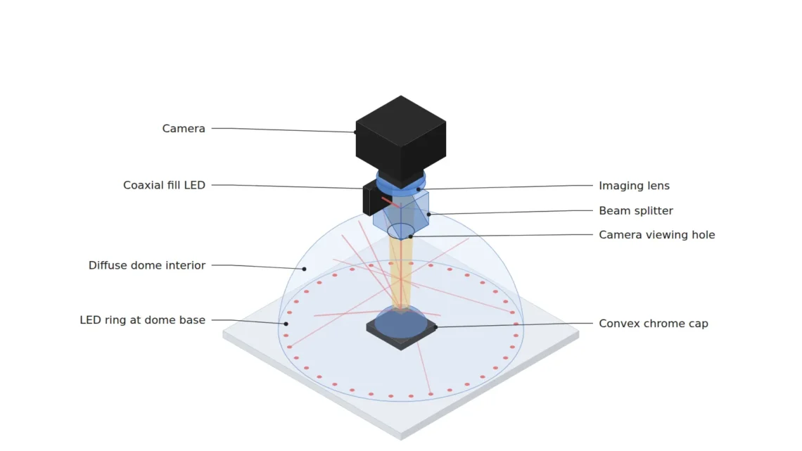
This dark spot is neither a defect nor a lighting fault but the image of the camera viewing hole reflected in a curved mirror. Because the cause is geometry, the solution also comes from geometry. The sequence is to calculate the dark spot size from the apparent angle of the viewing hole and the radius of curvature of the part, set the relationship between dome diameter and WD, and then combine coaxial auxiliary light that fills light in from the direction of the hole.
The dark spot of a dome light is not where the light is weak but where the camera sees itself.
1. A Dome Light Turns the Whole Sky into a Light Source
Point. Dome illumination works on curved specular parts not because of brightness but because it makes every normal direction of the part reflect a light-emitting surface of the same luminance.
Reason. On a specular surface, what the camera sees is not the surface itself but the reflected image in the direction the surface normal points to. A point whose normal is tilted by φ reflects the scene in the direction 2φ away from the optical axis. A curved surface has a continuous distribution of normal tilts, so under directional light only the few angles that see the light are bright and the rest are dark. A dome makes its entire inner diffusing surface glow at nearly the same luminance, so similar brightness comes back no matter which angle is reflected. Because shadows disappear as under an overcast sky, it is called cloudy-day illumination.
Example. When a chrome-plated connector shell mixing cylindrical faces and edge radii is imaged under a ring light, bright and dark bands alternate along the cylinder, and a 30 µm wide dent is buried at a band boundary. Place the same part inside a dome and the bands disappear, the whole surface settles to a similar gray, and the dent emerges as a small spot with a slope different from its surroundings. However, this is a highly reflective material whose reflection behavior changes greatly with plating thickness and gloss, so it cannot be confirmed before sample testing.
Point. The goal of dome design is not “brighter” but “filling every direction the part can reflect with the same luminance”. There are two directions in which this goal breaks, and the first is the camera viewing hole.
2. The Viewing-Hole Dark Spot — Its Size Can Be Calculated
Point. The size of the central dark spot on a convex specular part can be calculated from just the apparent angle of the viewing hole and the radius of curvature of the part.
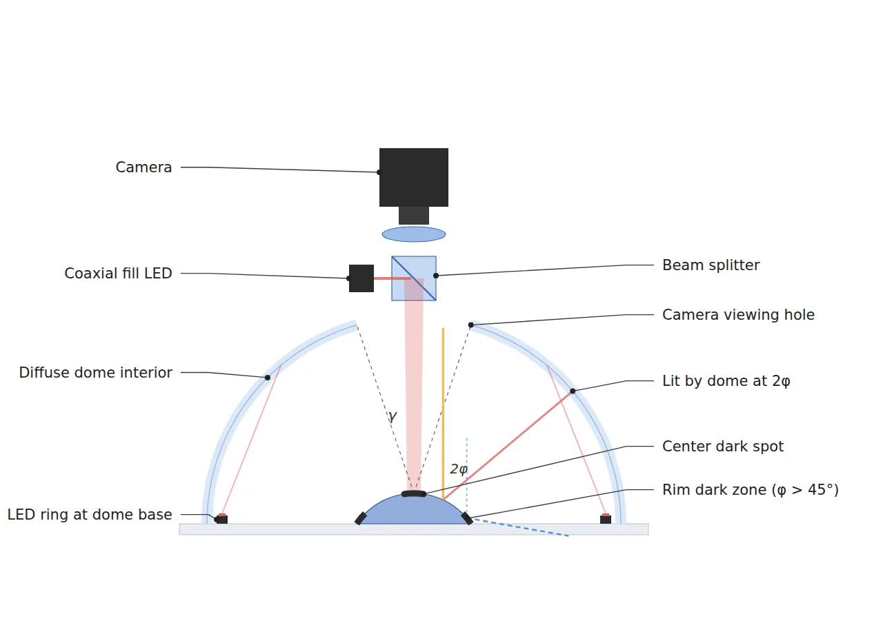
Reason. The viewing hole at the dome apex is an opening that emits no light. With hole diameter d and dome inner radius Rd, the half-angle of the hole seen from the part is γ = atan(d/2 ÷ Rd). A point with normal tilt φ reflects the 2φ direction, so the region where 2φ < γ, that is φ < γ/2, reflects the hole and is recorded as dark. On a convex surface with radius of curvature R, the radius of this region is R × sin(γ/2). The hole must be large enough not to clip the imaging beam, so it cannot be shrunk at will, and in the end the only way to shrink the dark spot is to enlarge the dome and reduce γ.
Example. Assume a convex metal cap with a 6 mm radius of curvature is imaged in a dome with a 180 mm inner diameter and a ø16 mm viewing hole. γ is about 5.1°, and the dark spot radius is 6 mm × sin(2.54°), about 0.27 mm, for a diameter of about 0.53 mm. At a pixel resolution of 6.54 µm/px this is a black circle about 81 px in diameter, large enough to cover dozens of 25 µm pinholes (about 3.8 px each). Shrinking the dome to a 120 mm inner diameter enlarges γ to about 7.6° and grows the dark spot to about 0.79 mm in diameter. Conversely, enlarging the dome pushes the WD out by the dome radius, since the camera must sit above the dome apex. Dome diameter is a variable that trades dark spot size against WD.
Point. Dome size can shrink the dark spot but cannot remove it. The spot diameter only falls roughly in inverse proportion to the dome radius; for it to reach zero, light must also come from the direction of the hole.
3. Combining Coaxial Auxiliary Light, and the Limit That Remains
Point. Placing a half mirror above the viewing hole and sending light down along the optical axis fills the place where the part reflects the hole with light, and the dark spot disappears. The key is not switching it on but matching its luminance to the dome interior.
Reason. From the part’s point of view, the hole must be part of the dome. If the coaxial auxiliary light is darker than the dome interior, a faint dark spot remains; if brighter, a bright circle remains instead, and either one causes over-detection. Moreover, the coaxial path passes the half mirror twice and returns at most 25% of the source output to the sensor, so the auxiliary light must be on a channel independent of the dome and its luminance adjusted separately. This is where the core insight of this article comes in. A dome has a second dark zone, and coaxial auxiliary light can never fill it. A point whose normal tilt exceeds 45° reflects a direction below the horizontal, so if the lower opening of the dome is at the part’s height, there is no light-emitting surface in that direction.
Example. On a cap with a 6 mm radius of curvature and a ø10 mm diameter, the radius corresponding to a 45° normal is 6 mm × sin 45°, about 4.24 mm. The ring from a radius of 4.24 mm to 5.0 mm, about 0.76 mm wide (about 116 px), stays dark no matter how the coaxial auxiliary light is adjusted. It is impossible to brighten this ring by software correction and inspect it, because the signal itself never arrives. This area must be separated from the inspection ROI and handed to a low-angle lighting station, or a structure that lowers the dome base below the part to place a light-emitting surface below the horizontal must be reviewed separately.
Point. A dome design document should not be a single line saying “uniform illumination” but a document that calculates and records two boundaries: the central dark spot (hole) and the outer dark zone (beyond 45°). The former is filled with coaxial auxiliary light; the latter is handled by ROI design.
Coaxial auxiliary light can fill the hole, but no dome can fill a curved surface that reflects below the horizontal.
4. Core Framework — Matching Table
| Category | Item | Specification / Parameter | Basis & Notes |
|---|---|---|---|
| ① Minimum defect size | Plating pinhole | Diameter 25 µm or more | Design assumption. Occupies about 3.8 px |
| ① Minimum defect size | Dent / scratch | Width 30 µm or more | Design assumption. Occupies about 4.6 px |
| ① Minimum defect size | Plating stain | Diameter 100 µm or more | Design assumption. Occupies about 15 px, low contrast |
| ② Optical setup | Illumination | Diffuse dome 180 mm inner diameter, ø16 mm viewing hole + coaxial auxiliary light on an independent channel | Margin over the imaging beam diameter at the hole, about 11.8 mm (calculated on the diagonal) |
| ② Optical setup | Dark-zone boundaries | Central dark spot about 0.53 mm diameter (without auxiliary light), outer dark zone beyond 4.24 mm radius | Calculated values. R × sin(γ/2), R × sin 45°, cap radius of curvature R = 6 mm |
| ② Optical setup | Lens | Focal length 50 mm, F/8 | Design assumption. Thin-lens object distance about 145 mm (magnification 0.528×) |
| ② Optical setup | WD (working distance) | 130 mm or more must be secured | Dome inner radius 90 mm + half-mirror module height 40 mm (design assumption). Confirm by measurement |
| ② Optical setup | Sensor & FOV | 2448 × 2048 px (3.45 µm pixel), FOV 16.0 mm × 13.4 mm, 6.54 µm/px | Calculated value. 16.0 mm ÷ 2448 px |
| ③ Algorithm | Coordinate transform | Polar unwrap about the cap center | Converts the concentric luminance distribution into a background uniform along each row |
| ③ Algorithm | Background model | Difference against a mean / standard-deviation template of 30 good parts | Re-acquire after adjusting auxiliary light luminance |
| ③ Algorithm | Detection threshold | Deviation from template > 4σ, area 9 px or more | Design assumption. Minimum blob of 3 × 3 px |
| ③ Algorithm | ROI separation | Ring beyond 4.24 mm radius goes to a separate station | Area with no signal. Not a correction target |
Table implication. A 25 µm pinhole occupies about 3.8 px at 6.54 µm/px and clears the detection premise, but without auxiliary light the central dark spot covers an area about 81 px in diameter and this figure loses its meaning. Conversely, the outer ring about 116 px wide cannot be recovered by any lighting adjustment, so the effective inspection area of this setup extends only to 4.24 mm of the 5.0 mm cap radius, about 72% by area. That is why effective inspection area must be calculated before resolution.
5. When the Opposite Approach Wins
- Flat specular parts: When the normal distribution is narrow, most of the dome’s wide emitting surface goes unused and only adds stray light. Coaxial illumination is smaller and gives higher contrast.
- When relief shapes or engraved-mark reading is the goal: A dome is a light that erases shadows, so it also erases the edge contrast that comes from height differences. Low-angle illumination is advantageous.
- Tight machine spaces where WD cannot be secured: Shrinking the dome enlarges the dark spot, and enlarging it pushes out the WD. If space does not allow this trade, review a method that lights several directions in sequence and composites the images.
The gloss and micro-texture of chrome plating vary with each plating condition, and the ranking between a dome and other methods can change, so this cannot be confirmed before sample testing.
Field Note
When I first installed a dome for plated cap inspection on a high-speed assembly line, a black circle of the same size appeared at the exact center of every part, and the initial judgment came out as rejects across the board. Even after adding coaxial auxiliary light, the center floated too bright for a while and over-detection continued in the opposite direction; it only settled once the auxiliary channel was separated and its gray level matched to the dome interior. Even then, the dark ring at the cap edge never went away. I think that had I calculated the 45° boundary back then, I would have split the ROI from the start, and I believe it is safer to recalculate this boundary for parts with a different curvature.
Field Checkpoints
- Is a WD of 130 mm or more secured by actual measurement — check including the dome inner radius and the height of the half-mirror module above the viewing hole.
- Have the surface material and reflectance of the target been identified first — the effect of a dome differs for chrome plating, nickel plating or a matte finish.
- Is the viewing hole large enough not to clip the imaging beam (on the diagonal) — under this assumption about 11.8 mm or more is needed.
- Have the central dark spot diameter and the 45° outer dark-zone radius been calculated from the part’s radius of curvature.
- Is the coaxial auxiliary light on an independent channel with its gray level matched to the dome interior.
- Does the pixel resolution let the minimum pinhole occupy 3 px or more — at 6.54 µm/px, 25 µm is the lower limit.

Noctvision
A machine vision engineer who fits cameras, lenses, lighting, and image-processing algorithms together for a living. Years spent on continuous production lines, vibration, heat, and dust included, working through diffuse reflection, contrast, and resolution differences too fine for a spec sheet to capture inform every post here, closing the gap between theory and the shop floor. Off duty, that same eye for light and lenses goes into repairing fully mechanical vintage film cameras.


You May Also Like
Specular Reflection Erases Defects: How Cross-Polarization Catches Missed Detections on Highly Reflective Surfaces
Can Correction Gain Erase Uneven Illumination? — The Limits of Flat-Field Correction and Designing Uniformity First