Is Coaxial Light Enough for Fine Scratches on Polished Metal? — Redesigning Coaxial Illumination Around Half-Mirror Loss and Tilt Tolerance
LIGHTING / OPTICS
When a polished aluminum panel or a mirror-finish stainless cover is imaged under an ordinary ring light, the surroundings appear on screen before any defect does. Ceiling lights, the lens barrel and the LED array of the light itself are mirrored into the image, and a fine scratch only about 20 µm wide disappears among those reflections. The most common first failure in specular metal inspection is not “the light is too weak” but “the surface reflects the light back instead of the defect”.
Left unaddressed, the cost appears in two directions at once. When the edges of reflections are read as defects, over-detections pile up and operators must re-inspect them by eye on the rework line; when the threshold is loosened instead, hairline-level scratches ship as they are. For specular parts whose cosmetic grade is the product value itself, a single such scratch leads to customer complaints and a full re-sort.
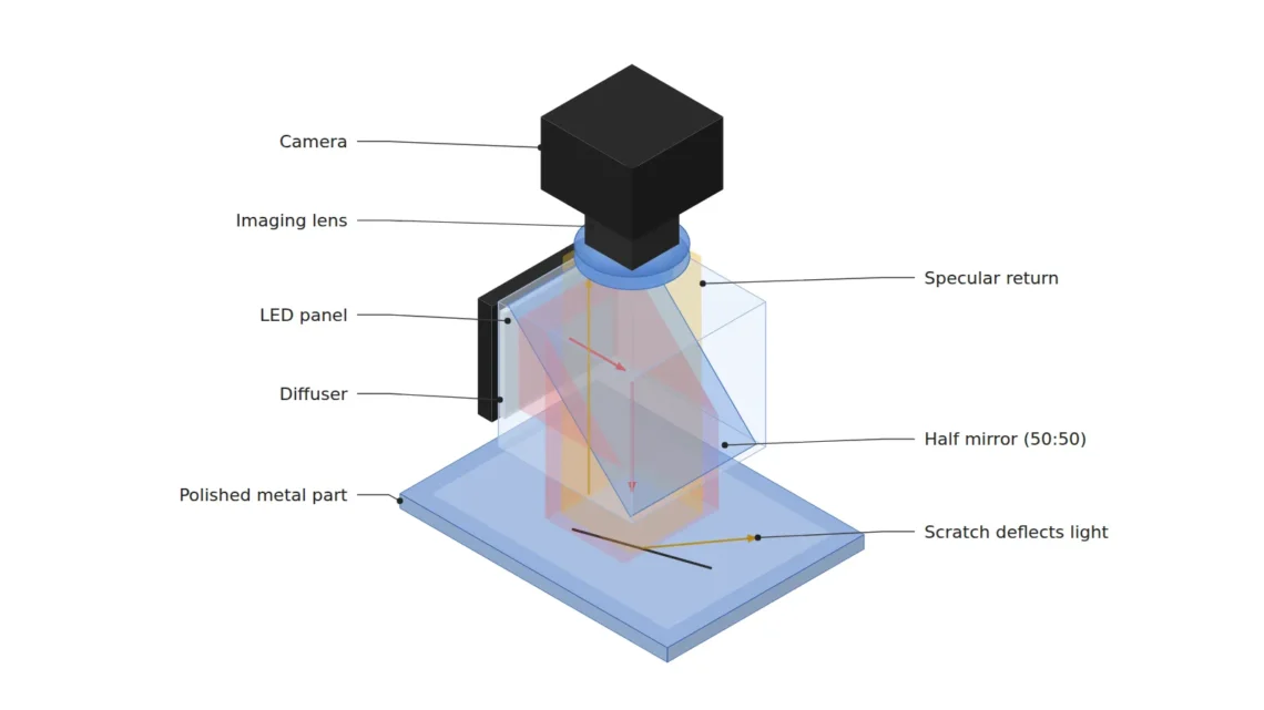
The physical solution is coaxial (on-axis) illumination, which aligns the illumination and viewing directions on one axis. When a half mirror sends light straight down along the optical axis, a flat specular surface returns the light directly into the lens and forms a uniform bright background, while the sloped walls of a scratch deflect the light out of the lens and remain as dark lines. This illumination is not free, however. Two constraints must be calculated first for the design to hold: the light loss of the half mirror and the surface tilt tolerance angle.
Under coaxial illumination, what separates a defect is not brightness but the slope of the surface.
1. Coaxial Illumination Is a Light That Builds a “Bright Background”
Point. The purpose of coaxial illumination is not to light up defects, but to make the normal surface as bright and uniform as possible so that defects drop out relatively dark.
Reason. A specular metal sends most of the incident light back in a single specular direction. When the light comes down parallel to the optical axis, the specular direction of a level surface points exactly back to the lens, and a bright background close to saturation forms on the sensor. A scratch is a narrow groove with sloped walls. Light reflected from a wall is deflected by twice the slope angle, leaves the lens aperture, and that spot is recorded as dark. In this structure, contrast is created not by the brightness of the defect but by the angle of the defect wall.
Example. Assume a setup that captures a mirror-polished aluminum panel in a FOV of 24.6 mm × 18.0 mm with a 4096 × 3000 px sensor and a 75 mm focal length lens. The pixel resolution is 24.6 mm ÷ 4096 px, or about 6.0 µm/px, so a 20 µm wide scratch becomes a dark line about 3.3 px wide. A line that could not be separated from the edges of the LED reflections under a ring light emerges as a continuous line on a uniform bright background under coaxial illumination. However, the actual reflection behavior of a specular material varies with polishing conditions and surface oxide, so this cannot be confirmed before sample testing.
Point. When reviewing coaxial illumination, the first question is not “how many lx are needed” but “how flat is the normal surface relative to the optical axis”. A dark defect only means something when the background is uniformly bright.
2. Surface Tilt Tolerance — The Fork Between Diffuse and Non-Diffuse Coaxial
Point. Coaxial illumination has a tolerance angle θmax meaning “a surface tilted up to this angle still looks bright”, and the presence or absence of a diffuser changes this value several-fold.
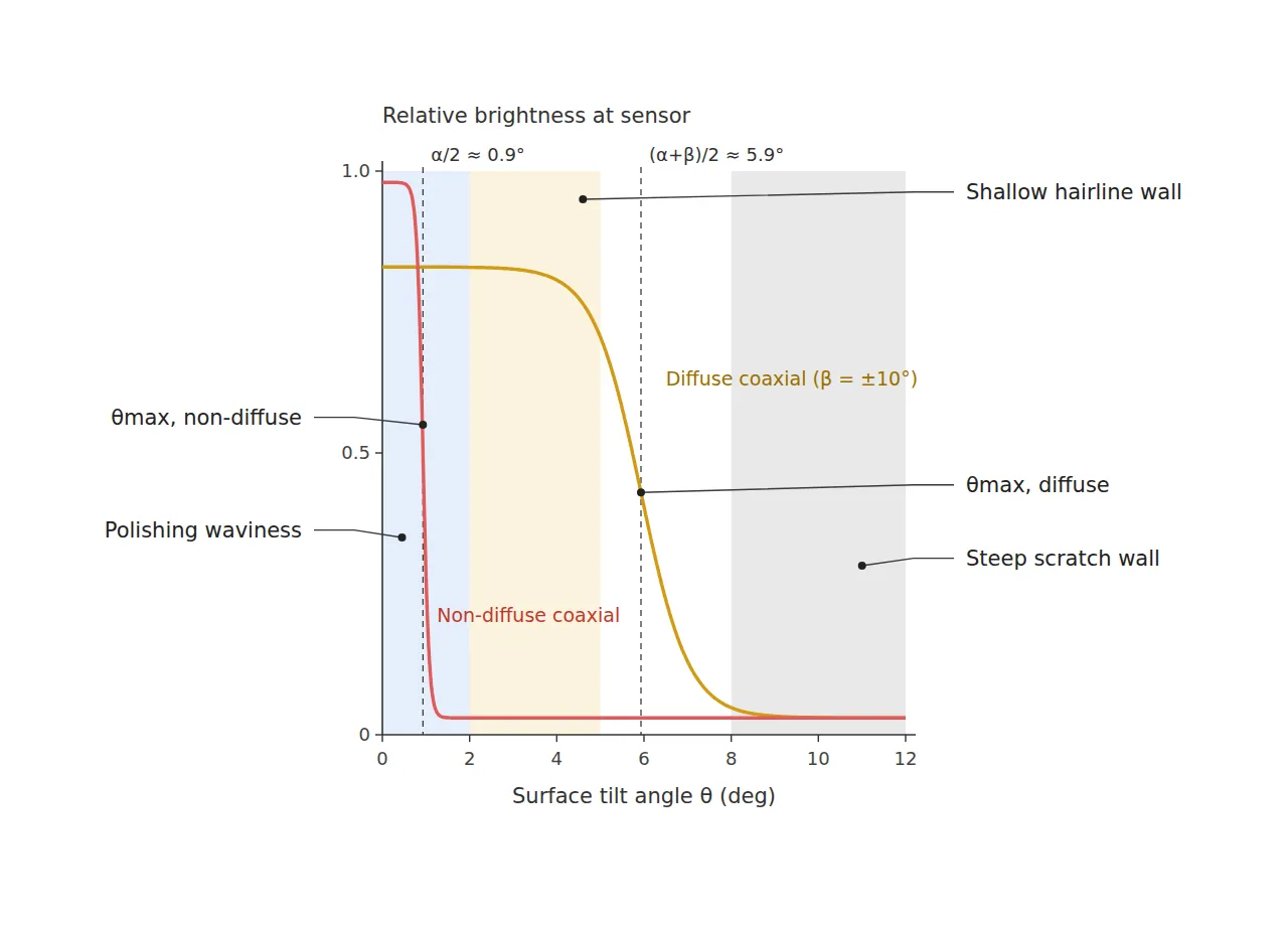
Reason. When the surface tilts by θ, the specular reflection is deflected by 2θ from the optical axis. If the object-side half-angle accepted by the lens is α, then under near-parallel non-diffuse coaxial light the surface looks bright only while 2θ < α, that is, up to θmax ≈ α/2. If a diffuser gives the illumination itself an angular spread of ±β, an incident direction that returns to the lens still exists for a tilted surface, and the tolerance widens to θmax ≈ (α + β)/2. A 75 mm focal length, F/5.6 lens has an entrance pupil of about 13.4 mm in diameter, and at an object distance of about 205 mm, α is about 1.87°. The tolerance of non-diffuse coaxial light is about 0.9°, and the tolerance of diffuse coaxial light, assuming a diffusion spread of ±10°, is about 5.9°.
Example. A polished aluminum panel carries gentle undulation (waviness) left by the polishing process. Under non-diffuse coaxial light, an undulation of just over 1° is enough to create dark blotches in the background, and these blotches are over-detected as signals of the same kind as scratches. Switching to diffuse coaxial light brings the undulation inside the tolerance angle and evens out the background, but very shallow hairline scratches whose wall slope is only a few ° also turn bright, and contrast falls. It must also be checked that, under non-diffuse coaxial light, a part tilted by only 1° on the fixture can darken the entire frame. Control of the fixture posture itself requires a separate review.
Point. This is where the core insight of this article comes in. θmax is a physical slope filter performed by the illumination, and it sets the boundary between “normal undulation” and “defect wall” before any algorithm does. Choosing a diffuser is not a brightness option but a design act that decides in hardware from which slope onward a feature counts as a defect.
A diffuser is not a part that selects brightness but a part that selects the minimum slope angle to be seen as a defect.
3. Half-Mirror Light Loss — The 25% Ceiling and Stray Light
Point. Coaxial illumination with a 50:50 half mirror returns at most 25% of the source output toward the sensor. This loss is a structural ceiling that does not go away no matter how carefully the setup is refined.
Reason. The light passes the half mirror twice. Going down, 50% remains by reflection; coming back up from the surface, another 50% remains by transmission, so 0.5 × 0.5 = 0.25. The remaining 75% does not vanish but becomes stray light inside the illuminator box. The 50% that is transmitted through the half mirror at first strikes the opposite wall of the box, and half of the returning light is reflected toward the source. When this light bounces again off the inner walls or the back face of the half mirror and enters the lens, it lays a faint veil over the background and erodes contrast.
Example. At the same source output, the background brightness through a coaxial box is a quarter or less of that under direct illumination, so in setups that need short exposures, strobe drive to raise the instantaneous output is usually reviewed first. In addition, a thick plate half mirror tilted at 45° in the imaging path can introduce astigmatism and a double image from back-face reflection, so it is safer to specify a pellicle or cube half mirror together with anti-reflective black treatment of the inner walls. This stray light cannot be fully removed by software image processing alone, because the veil component arrives in the same pixels as the defect signal.
Point. Light budget design for coaxial illumination is work that first decides “where to absorb the lost 75%” rather than “how bright a source to buy”. Light loss can be compensated with output, but unabsorbed stray light grows along with the output.
4. Core Framework — Matching Table
| Category | Item | Specification / Parameter | Basis & Notes |
|---|---|---|---|
| ① Minimum defect size | Fine scratch on mirror-polished surface | Width 20 µm or more, length 300 µm or more | Design assumption. Occupies about 3.3 px in width and about 50 px in length |
| ① Minimum defect size | Point dent (pit) | Diameter 40 µm or more | Design assumption. Occupies about 6.7 px |
| ② Optical setup | Illumination | Diffuse coaxial illumination, 50:50 half mirror (pellicle or cube) | Ceiling of light reaching the sensor 25% (0.5 × 0.5). Anti-reflective black inner walls |
| ② Optical setup | Surface tilt tolerance | Diffuse coaxial about 5.9° / non-diffuse coaxial about 0.9° | Calculated value. θmax ≈ (α + β)/2, α ≈ 1.87°, β = ±10° (design assumption) |
| ② Optical setup | Lens | Focal length 75 mm, F/5.6 | Design assumption. Entrance pupil diameter about 13.4 mm |
| ② Optical setup | WD (working distance) | 180 mm or more must be secured | Thin-lens object distance about 205 mm (magnification 0.575×). Confirm by measurement including coaxial box height |
| ② Optical setup | Sensor & FOV | 4096 × 3000 px (3.45 µm pixel), FOV 24.6 mm × 18.0 mm, 6.0 µm/px | Calculated value. 24.6 mm ÷ 4096 px |
| ③ Algorithm | Background correction | Flat-field correction with an image of a defect-free specular reference plate | Removes illuminance non-uniformity of the coaxial box and the static part of the stray-light veil |
| ③ Algorithm | Dark defect enhancement | Black-hat morphology, 11 px kernel | Kernel larger than the largest target (pit about 6.7 px) |
| ③ Algorithm | Detection threshold | Brightness drop of 30% or more versus local background | Design assumption. Re-estimated with 30 good parts |
| ③ Algorithm | Shape filter | Linear defect length 50 px or more, point defect area 9 px or more (3 × 3) | From ①: 300 µm ÷ 6.0 µm/px = 50 px |
Table implication. At 6.0 µm/px, a 20 µm wide scratch occupies about 3.3 px, only just above the 3 px detection premise, so the margin of this setup lies less in the optics than in the illumination tolerance angle. A scratch whose wall slope is gentler than the diffuse-coaxial θmax of about 5.9° can look bright and be missed even if it is wide enough, while the non-diffuse-coaxial value of about 0.9° lets a 1° fixture tilt collapse the background. That is why pixel resolution and tolerance angle must be checked together in one table.
5. When the Opposite Approach Wins
- Parts with large curvature or a wide range of surface tilt: On curved surfaces whose tilt exceeds the tolerance angle several times over, the bright background of coaxial illumination itself cannot be maintained. A dome light that supplies light from a wide range of angles is advantageous.
- Directional hairline-machined surfaces (brushed finish): The machining lines themselves have slope, so under coaxial light the background fills with streaks. Low-angle illumination orthogonal to the streaks, or dark field, produces cleaner contrast.
- Diffuse surfaces such as bead-blasted finishes: On surfaces with weak specular reflection, the bright coaxial background does not form and only the 25% light loss remains. Oblique illumination is more economical in both light budget and contrast.
The reflection behavior of specular metals and the wall slope of scratches vary greatly with polishing conditions, coatings and oxide films, so whether coaxial or another method wins cannot be confirmed before sample testing.
Field Note
In a specular metal cover inspection on a high-speed assembly line, I once started with non-diffuse coaxial light and ran into one side of the frame going dark every time a part seated on the fixture tilted by around 1°. Adding a diffuser to widen the tolerance angle stabilized the background, but this time the contrast of shallow hairline scratches dropped noticeably. Only after switching to a diffuser one step narrower in spread and re-tuning the black-hat kernel and threshold could we find a balance point. What I took from that was that the tolerance angle is not an optical spec but the defect criterion itself, and I believe even that balance point has to be re-checked whenever the material changes.
Field Checkpoints
- Is a WD of 180 mm or more secured by actual measurement — check including the coaxial illuminator box height, the front of the lens barrel and the clearance above the top of the part.
- Have the surface material and reflectance of the target been identified first — whether coaxial works depends on whether it is specular, hairline or diffuse finish.
- Has the surface tilt tolerance θmax been calculated from the lens aperture half-angle α and the diffusion spread β.
- Does the part tilt when seated on the fixture fall within θmax — with non-diffuse coaxial light, control to 1° or less is needed.
- Has the stray-light veil been suppressed through the half mirror type (pellicle or cube) and black treatment of the box interior.
- Does the pixel resolution let the minimum scratch width occupy 3 px or more — at 6.0 µm/px, 20 µm is the lower limit.

Noctvision
A machine vision engineer who fits cameras, lenses, lighting, and image-processing algorithms together for a living. Years spent on continuous production lines, vibration, heat, and dust included, working through diffuse reflection, contrast, and resolution differences too fine for a spec sheet to capture inform every post here, closing the gap between theory and the shop floor. Off duty, that same eye for light and lenses goes into repairing fully mechanical vintage film cameras.

You May Also Like
There Are Defects That Vanish in Visible Light — Inspection Design Beyond the 1 μm Barrier in SWIR Imaging
Can Correction Gain Erase Uneven Illumination? — The Limits of Flat-Field Correction and Designing Uniformity First