Six Machine-Vision Lighting Methods and How to Choose
LIGHTING
Mount a 30 mm radius ring light at lens height, and a flat gold-plated pad shows a bright ring only on a circle 15 mm from the center of the view.
Taking a 50 μm wide scratch on a PCB gold pad as the target, I calculated which surface tilts each of the six lighting methods turns into brightness, all from one line for the mirror-image position, x = r × u ÷ (u + H).
About 15 min read
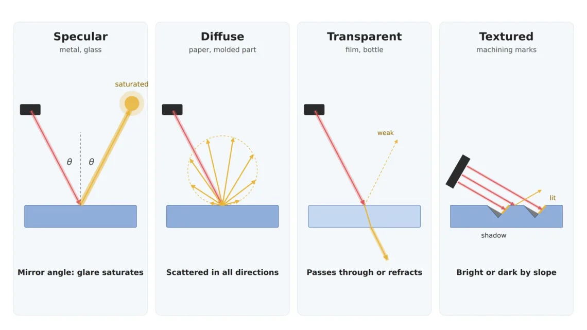
The target is a PCB where gold-plated pads show through green solder mask. Solder mask is a diffuse reflection1 surface that scatters incoming light in many directions, while a gold pad is close to a specular reflection2 surface that throws light back in one direction at the angle it arrived, so the two differ sharply in brightness under the same light. The defect to find is a 50 μm wide scratch on a pad. I write down the reflective character of both surfaces before deciding on lighting because, on a specular surface, what the camera records is less the pad itself than the light source mirrored in it.
Choose lighting from catalog photos and the cost shows up on the algorithm side. If, under a ring light, only the pads around 15 mm from the center of the view flash while the rest sink into darkness, setting the threshold for the dark pads makes the reflections on the bright pads register as defects, and setting it for the bright pads makes the scratches on the dark pads disappear. Stacking filters does not bring back contrast3 that was never captured. Loosen the judgment to restart a line stopped by false rejects, and the next cost comes back as shipped defects.
The way out starts with an angle calculation. Each lighting method has a set range of surface tilts that send light back into the lens, and on a specular surface that range follows from where the mirror image of the light source lands. When I choose lighting, I do this calculation before looking at catalog photos. All six methods solve with the same formula, and once the calculation is done, the candidates that can turn this scratch into a brightness difference narrow to two.
A 50 μm scratch barely clears three pixels on screen
The calculation starts from the camera and the view. Assume a camera 2,448 px wide with 3.45 μm pixels: the sensor is 8.45 mm wide, and with a 40 mm wide view, the length one pixel covers on the pad, the object-side pixel resolution4, is 16.3 μm. A 50 μm wide scratch spans 3.06 pixels. My rule is that the smallest defect spans at least three pixels, and this setup barely clears it. With a 25 mm lens, a magnification of 0.211 puts the pad about 143 mm from the lens center, and that distance is the reference for every angle calculation that follows.
Up to here the numbers have nothing to do with lighting. Even with three pixels secured, if those three pixels are no brighter or darker than the neighboring pad, the defect might as well not be on screen. The lighting, and not the lens, is what creates the brightness difference, and where that difference comes from splits in opposite directions depending on the kind of surface.
| Surface | Light behavior | What the camera records | On this board |
|---|---|---|---|
| Specular (gold-plated pads, machined metal, glass) | Reflects in one direction at the angle of incidence | The shape and position of the light source mirrored in the surface | Gold pads |
| Diffuse (solder mask, matte molded parts, paper) | Scatters in many directions | Light intensity and surface color | Solder mask |
| Transparent (film, glass substrates) | Passes through or refracts | The background behind it and refracted edges | None |
| Relief (machining marks, bumps, dents) | Reflection direction changes with tilt | Light and shadow made by tilt and height | Scratches, particles |
This defect sits where the first and last rows of the table overlap. It is relief on a specular surface, so it shows bright or dark depending on whether the tilt of the scratch walls puts the mirror image of the light source inside the lens or outside it. Assume the 50 μm wide scratch is 3 μm deep, and its V-shaped walls tilt by 6.84°. How each of the six lights handles those 6.84° decides the choice.
On a specular surface the camera sees the mirror image of the light
A flat specular surface reflects the scene above it like a mirror. With the camera at height u and a light source of radius r at height H, the mirror image5 of the source forms at depth H below the surface, and the camera sees that image at the point x = r × u ÷ (u + H) on the surface. The formula comes from one pair of similar triangles, and the ring that a ring light leaves, the dark spot of a dome light and the area a coaxial light illuminates all come out of this one line.
Mount a 30 mm radius ring at lens height (H = u = 143 mm) and x = 30 × 143 ÷ 286 = 15 mm. A flat pad flashes only when it sits on the circle 15 mm from the center of the view, where it picks up the mirror image of the ring, and pads inside or outside that circle stay dark. The same pad changes brightness with its position, so a single threshold cannot make the call. Lower the ring to 50 mm above the pad and x becomes 22.2 mm, past the 20 mm half-width of the view, so the ring leaves the frame; in exchange the whole flat pad goes dark and, at the center of the view, only faces tilted by 15.5° send light back. One ring moves between bright field6 and dark field7 with nothing but its height.

The six panels of the figure differ only in where the light source sits. Relative to the gray camera, the yellow light either surrounds the front, comes in at a slant from the side, overlaps the optical axis through a half mirror, shines from behind, covers the whole hemisphere or arrives almost flush with the surface, and that direction sets which surface tilts send light back into the lens.
A dome light8 glows over its whole inner hemisphere, so flat pads and tilted faces alike come out evenly bright. The camera hole at the top gives no light, though, so with a 10 mm radius hole 100 mm above the pad, x = 10 × 143 ÷ 243 = 5.9 mm, and the hole shows as a dark spot on flat pads within a 5.9 mm radius of the center of the view.
15mm
Radius of the ring reflected on a flat pad by a 30 mm radius ring at lens height
62.3mm
Emitting window width a coaxial light with an 80 mm optical path needs to light a 40 mm wide view to its edges
37.5°
Surface tilt that sends light back into the lens under a low-angle light at 15° elevation
A coaxial light9 places the source on the optical axis through a half mirror, so the same formula sets the bright area. With a 50 mm wide emitting window at an optical path of 80 mm from the pad, only up to x = 25 × 143 ÷ 223 = 16.0 mm is lit, and flat pads beyond it record as dark. Lighting a 40 mm wide view to its edges takes an emitting window of at least 62.3 mm. The requirement that the window be larger than the view turns into a number with this one line.
The tilts each of the six methods turns into brightness
If the mirror-image formula sets the brightness of flat surfaces, the law of reflection sets the brightness of tilted ones. A face tilted by t bends the reflected light by 2t, so light arriving from a direction a away from the lens axis is sent into the lens by faces tilted by a ÷ 2. Lined up on that basis, the six methods compare as in the table below.
| Method | Where the light comes from | Faces that send light into the lens | Suited inspection |
|---|---|---|---|
| Ring light | From around the lens, head-on (30 mm radius at lens height is 11.8° off axis) | Flat faces only on the 15 mm ring; tilted faces near 5.9° | Shape on diffuse surfaces, part presence |
| Bar light | At a slant from one side | Faces tilted toward the source; height shows as shadow | Relief, engraving, height steps |
| Coaxial light | Overlapping the lens axis through a half mirror | Faces tilted by about 8.7° or less at the center of the view (50 mm window, 80 mm optical path) | Scratches, particles and engraving on flat specular surfaces |
| Backlight | From behind the target | No surface information, outline only | Outer dimensions, hole positions |
| Dome light | From the whole hemisphere | Almost every tilt (dark spot of the camera hole at the center) | Print and labels on curved specular surfaces |
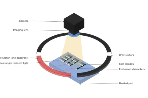
| Low-angle light | At a low angle close to the surface (15° elevation) | Faces standing near 37.5°, rough edges that scatter light | Fine scratches, particles, cracks |
Follow the 6.84° scratch walls through the table and a fork appears. Under a low-angle light at 15° elevation10, light striking those walls bounces off in a direction 61.3° from vertical and misses the lens. For the scratch to rise bright over a pad sunk into a dark background, it needs faces standing close to 37.5° or rough edges that scatter light. If burrs stand along the scratch edges or its floor is rough, this dark-field method gives the highest contrast.
Under a coaxial light it goes the other way: 6.84° falls inside the 8.7° tilt window at the center of the view. If the walls are smooth, they stay as bright as the flat pad and the scratch disappears; it records as a dark line only when its rough floor scatters light. Shrink the emitting window to narrow the tilt window below 6.84°, and now the edges of the view go dark. Lighting the whole 40 mm view while narrowing the window takes an optical path of about 192 mm and an emitting window of about 94 mm or more, so in that situation I stop insisting on a regular lens and consider a telecentric lens11 paired with collimated coaxial light. In a telecentric lens the object-side rays run parallel to the optical axis, so widening the view and narrowing the tilt window stop holding each other back.
The other three methods are far from this scratch. A backlight records only the silhouette of the board, so it carries no pad surface information, but when measuring hole positions and outer dimensions it gives the sharpest outline of all the methods. Here the evenness of the backlight governs dimensional accuracy: where its edge is darker, the outline on that side is picked up shifted inward. A dome light makes every tilt bright, which erases the difference between scratch walls and pad, but it is strong for reading print on curved surfaces whose reflection directions vary, such as cans or crinkled labels. A bar light earns its place when you look at height on diffuse surfaces, such as a particle standing on solder mask.
Shadow length and angle error grow together
A bar light reveals height through shadow. When a bump of height h receives light at elevation e, its shadow is h ÷ tan e long. For a 50 μm tall particle on solder mask, that is 50 μm (3.06 pixels) at 45°, 86.6 μm (5.3 pixels) at 30° and 137.4 μm (8.4 pixels) at 20°. Lowering the angle lengthens the shadow and adds pixels, but the difference made by the same 2° error grows along with it.
At 30° elevation, a 2° error changes the shadow by 6.6 μm to 7.4 μm, less than half a pixel. At 20°, the same 2° moves it by 13.6 μm to 16.5 μm, nearly a full pixel. If particle size is judged by shadow width, a bracket that wobbles by 2° is enough to shift the judgment boundary by one pixel. So I write down the angle and height of bar and low-angle lights as numbers and mount them on fixed brackets that do not turn when one screw loosens.
A low-angle ring is touchy for the same reason. Making 15° elevation with a 50 mm radius ring puts the ring 13.4 mm above the pad, and at a point 20 mm out at the edge of the view, the elevation spreads to 24.1° on the near side and 10.8° on the far side. The tilt that sends light back also scatters from 33.0° to 39.6°, so scratch brightness at the center and at the edge of the view may not match. Keeping the judgment area close to the center of the ring is the safer choice.
Brightness is set after the angles are fixed. In a coaxial light the light passes the half mirror twice, so with a 50:50 half mirror at most 25 % of the light leaving the source returns to the camera, and the source must be brighter than in other methods to make up for it. Turn the output all the way up, though, and the brightest pads saturate12, flattening the scratches inside them to the same value. My rule is that the brightest pixel on a normal pad stays at or below 230 in 8 bits, and ambient light such as ceiling lamps or indicator lights on the next machine gets blocked with a light-shield cover.
Matching a lighting setup to gold pad scratches
Gathering the calculations, I line up the candidates for this scratch on the same camera and lens. The optics column keeps the camera and lens fixed and swaps only the lighting, and the algorithm column follows the brightness distribution each light creates, down to whether it looks for bright or dark pixels.
| Lighting setup | ① Minimum defect size | ② Optics · lighting · WD | ③ Algorithm parameters |
|---|---|---|---|
| Ring light at lens height | 50 μm wide = 3.06 px (16.3 μm/px) | 2,448 px, 3.45 μm pixels, 25 mm lens, WD about 143 mm (from lens center), 30 mm radius ring | Flat pad brightness splits with the position of the 15 mm ring, so a single fixed threshold cannot judge. Not used for this defect |
| Low-angle ring at 15° elevation | 50 μm wide = 3.06 px, scratch with rough edges | Same camera and lens, 50 mm radius ring mounted 13.4 mm above the pad, judgment area toward the ring center | Look for bright lines on a dark pad. Group pixels exceeding the pad mean brightness by a set margin as candidates and treat 3 px wide and 6 px long or more as a defect (assumed) |
| Coaxial light, window 62.3 mm or wider | 50 μm wide = 3.06 px, scratch with a rough floor | Same camera and lens, 80 mm optical path, 50:50 half mirror (at most 25 % of the light), check that the coaxial unit body fits within the WD | Look for dark lines on a bright pad. Group pixels falling below a set fraction of the pad mean brightness as candidates and exclude saturated pixels from the judgment |
In the table, the three rows have nearly identical optics columns while the algorithm column flips the direction it searches. Under low-angle light the defect candidates are pixels that rise bright; under coaxial light they are pixels that drop dark, so changing the lighting changes the judgment code too. Conversely, for an inspection that looks at the height of particles on solder mask instead of scratches, a bar light from one side at 30° is simpler and cheaper. Whether the scratch edges on a strongly specular surface such as gold plating actually scatter light cannot be guaranteed before a sample test.
If I had to pick one of the two candidates, I would shoot low-angle first. Even if the board warps a little and a pad tilts by about 1°, the reflection still misses the lens and the background stays dark, whereas with a coaxial window fitted exactly to the view, a pad at the edge of the view goes dark when it tilts outward even slightly. If there is time to spare in the cycle, another option is to mount both lights and switch which one fires on alternate shots, judging from two images.
What shrinks when lighting comes first
I write the lighting selection order like this. Split the surfaces into specular and diffuse, write down the tilt or height the defect creates as a number, calculate each method’s tilt window with the mirror-image formula and the law of reflection, and then shoot samples only with the methods whose window contains the defect. The camera and lens can be decided after that without losing anything. Changing even one angle of lighting installed in a machine means stopping the line, so a single page of calculation saves cost at the cheapest stage.
Keeping the lighting spec in numbers also makes the decision easier for whoever decides on the equipment purchase. The light fixture costs less than the camera, but the price of choosing the wrong light grows into weeks of algorithm tuning and re-inspection staff. This article explains technology and is not investment advice. See our Disclaimer.
Field Note
When setting up a new gold pad inspection station, before settling on the lighting I place the same board alternately at the center and the edge of the view and take two shots under the ring light to see first how much pad brightness splits by position. A large split is a sign that the mirror-image calculation holds, so I shoot the same two positions again under low-angle and coaxial light and write down the brightness difference between scratch pixels and pad pixels as 8-bit values. The judgment criterion comes from the position where that difference is smallest.
Field Checkpoints
Once the brightness differences under both lights are written down as numbers, put the setup through the questions below before it goes into the spec.
- Do the coaxial unit body or the low-angle ring fit within the WD of about 143 mm (from lens center) without interfering with the lens? (Has the WD reference plane in the lens spec sheet been confirmed as the front face?)
- With the low-angle ring 13.4 mm above the pad, does it clear tall components and fixture clamps?
- Is the coaxial emitting window at least 62.3 mm wide for a 40 mm wide view? (This assumes an 80 mm optical path; a longer path needs a larger window.)
- Do the ring reflection and the dome dark spot stay out of the judgment area? (Were their positions calculated in advance with x = r × u ÷ (u + H)?)
- Are the lighting angles and heights written down as numbers and mounted on fixed brackets? (At 20° elevation a 2° wobble moves the shadow by about one pixel.)
- Does the brightest pixel on a normal pad stay unsaturated, and does a light-shield cover block ambient light?
- Were both lights compared on real boards? (Scattering at scratch edges is not decided by calculation alone.)
Frequently Asked Questions
What should be decided first when choosing lighting?
Whether the target surface is specular or diffuse, whether the defect creates tilt or height, and how many degrees and μm that tilt and height are. With those numbers, the methods whose tilt window contains the defect narrow to two or three of the six, and the camera and lens only need to be chosen to capture the contrast that lighting creates.
Which lighting suits highly reflective metal surfaces?
For scratches and particles on flat metal, the starting points are coaxial light, which lifts the background bright, and low-angle light, which sinks it dark. On curved surfaces the reflection directions vary, so a dome gives even brightness, though relief stops showing to the same degree. Either way, calculating the emitting window size and height with the mirror-image formula cuts the number of trial shots.
Does brighter lighting improve detection?
Brightness is a value set after the angles are fixed. Turning the output all the way up saturates the brightest pads and flattens the scratch information inside them to the same value, so it is safer to leave headroom below the maximum brightness of a normal pad when setting exposure.
Glossary
- [1] Diffuse reflection diffuse reflection
Reflection in which light hitting a rough surface scatters in many directions. Solder mask and matte molded parts come close to it. ↩ - [2] Specular reflection specular reflection
Reflection in which incoming light bounces off in one direction at the same angle as it arrived. Mirrors, glass and gold-plated surfaces come close to it. ↩ - [3] Contrast contrast
The brightness difference between defect pixels and the pixels around them. Lighting creates it; the camera and the algorithm capture and amplify it. ↩ - [4] Object-side pixel resolution object-side pixel resolution
The length one pixel covers on the object. It is the view divided by the horizontal pixel count, written in μm/px. ↩ - [5] Mirror image mirror image
The apparent image of a light source formed behind a flat mirror surface. If the source is H above the surface, the image forms H below it. ↩ - [6] Bright field bright field
A lighting arrangement in which light bouncing off flat areas enters the lens, so the background records bright. Defects usually look dark. ↩ - [7] Dark field dark field
A lighting arrangement in which light bouncing off flat areas misses the lens, so the background records dark. Only defects that scatter light or tilt steeply rise bright. ↩ - [8] Dome light dome light
A light that emits or reflects from the inside of a hemisphere and illuminates from almost every direction. It casts almost no shadows. ↩ - [9] Coaxial light coaxial light
A light that bends the source light with a half mirror to illuminate along the same direction as the lens axis. The light passes the half mirror twice, so the loss is large. ↩ - [10] Elevation angle elevation angle
The angle between the direction of incoming light and the surface. The closer to 0°, the more the light grazes the surface. ↩ - [11] Telecentric lens telecentric lens
A lens whose object-side chief rays run parallel to the optical axis. Paired with collimated lighting, it can turn very small tilts into brightness differences. ↩ - [12] Saturation saturation
The state in which a pixel reaches the maximum brightness it can hold. In 8 bits, light brighter than 255 is recorded as the same value. ↩
References
- Formulas: law of reflection (a face tilted by t bends the reflected light by 2t); mirror-image position x = r × u ÷ (u + H); shadow length = h ÷ tan(elevation angle); thin-lens equation 1/f = 1/u + 1/v with magnification m = sensor width ÷ view gives u = f × (1 + 1/m); pixel size = view ÷ horizontal pixel count
- General principles of the law of reflection and the thin-lens equation: E. Hecht, Optics, 5th ed., Pearson, 2017
- Assumed values: a 2,448 × 2,048 px camera with 3.45 μm pixels, 25 mm lens, 40 mm wide view, 30 mm ring radius, dome camera hole of 10 mm radius at 100 mm height, coaxial window 50 mm wide at an 80 mm optical path, 3 μm scratch depth and a 50:50 half mirror are assumptions for the worked example
Related reading — How to Handle Imaging on Highly Reflective Surfaces · A Dark-Field Ring Light Tolerates Far More Tilt Than Coaxial Light · One Lighting Angle Decides the OCR Read Rate on Molded Characters

Noctvision
An engineer who has handled mechanical design and project management for production equipment since 2005. Here I work through the cameras, lenses and lighting that go into equipment with formulas and public data, and record the assumptions and sources alongside the numbers.

You May Also Like
Changing the Sensor Means Recalculating the Illumination
Coaxial Light Alone Does Not Settle Fine Scratches on Polished Metal