Specular Reflection Erases Defects: How Cross-Polarization Catches Missed Detections on Highly Reflective Surfaces
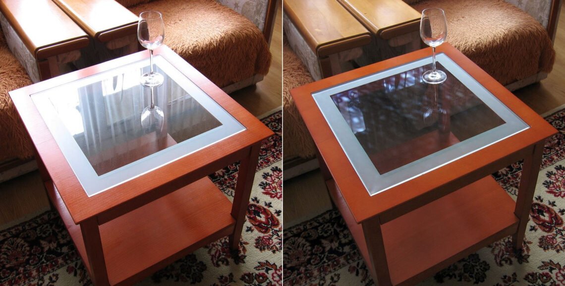
At an inspection station where a matte injection-molded housing sits next to a nickel-plated connector pin, trying to capture both materials at once under the same lighting condition almost always runs into trouble on the connector side. Specular reflection from the plated surface saturates the camera’s exposure, and any scratch or foreign matter sitting on top of it gets buried in the highlight and disappears. No matter how finely the lighting angle is tuned, if the surface is close to mirror-like, it is difficult to fully avoid specular reflection itself.
Leaving this unaddressed leaks cost in two directions. One is that a defect buried in a highlight slips through as a missed detection and leaks out to the next process or to the customer. The other is that pushing detection sensitivity up to compensate ends up falsely flagging the highlight boundary itself as a defect, rejecting good product. In both cases the root cause is the same: only the ‘intensity’ or ‘angle’ of the lighting was adjusted, while the third variable — the ‘polarization state’ of the light — was never addressed. This article organizes how cross-polarization filtering physically blocks specular reflection, and when this method is favorable or unfavorable.
Why specular reflection is hard to fix with software correction
When light strikes a mirror-smooth metal, plated, or glass surface, the specular-reflection component, unlike diffuse reflection, bounces back strongly only in the narrow direction where the angle of incidence equals the angle of reflection. This specular light tends to carry a strong polarization component even under ordinary unpolarized illumination, and recent research has quantitatively analyzed that specular reflection off a metal surface in particular contains a significant circular-polarization component. The problem is that this specular reflection locally saturates the camera sensor and wipes out the brightness information itself. An error that only shifts geometric position, like distortion, leaves room for software correction, but a saturated pixel has physically lost the brightness and color information of whatever defect was originally there, and it cannot be recovered through post-processing.
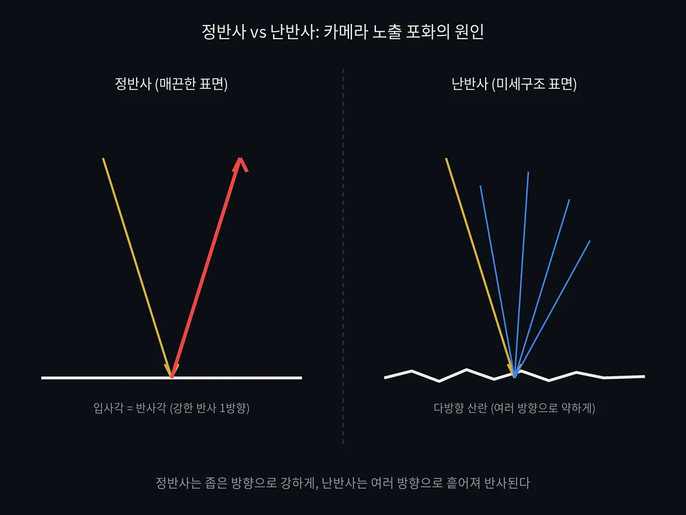
Cross-polarization solves this problem optically — that is, at the stage before light ever reaches the camera. Placing a polarizer in front of the illumination and an analyzer in front of the lens, with the two polarization axes set orthogonal to each other (90°), blocks the specular component, which retains its polarization direction as reflected off the surface, from passing through the analyzer, while only the diffuse component, whose polarization has been scrambled by the surface’s microstructure, passes through to the lens. CN103743758A is a case that applies this principle directly to a high-reflectivity metal surface inspection system, and US10228331B2, in semiconductor wafer inspection, likewise takes the approach of blocking specular reflection and collecting mainly scattered light to raise defect-detection sensitivity.
The trade-off of introducing a polarizer: light loss and contrast
Cross-polarization is not free. A significant portion of the total light is lost passing through the polarizer and analyzer, and the further the orthogonal angle between the two polarization axes drifts from exactly 90°, the more the balance shifts between the specular-suppression effect and the light that remains. A method has in fact been proposed for finding the optimal polarization angle by tracking changes in the brightness distribution of the highlight region through grayscale histogram analysis, and it is used as the basis for experimentally tuning the polarizer’s rotation angle on sites with complex lighting conditions. Patents such as US8400629B2 propose a structure that uses a wave plate to switch between S-polarization, P-polarization, and circular polarization depending on the situation — which also implies that a single polarization angle alone may not be enough, depending on the material or defect type.
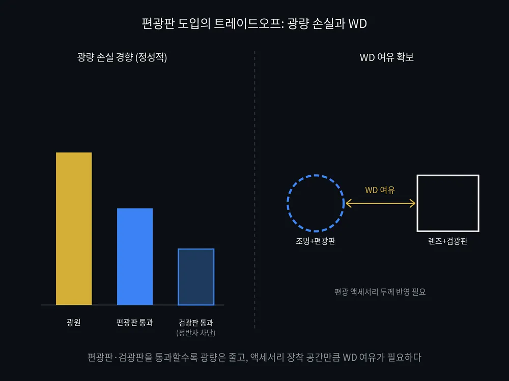
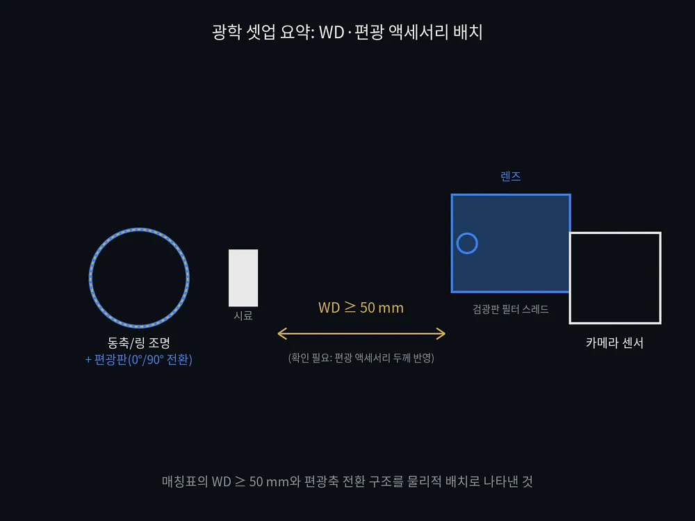
So the moment a polarizer is introduced, illumination intensity needs to be boosted to compensate, which affects lighting-module selection in terms of heat, lifespan, and power consumption. The polarizer itself also occupies physical space between the lens and the lighting, so unless WD (working distance) is given enough margin, mounting the polarizer at all can become physically impossible. This is why, when setting lens specifications, the clearance needed for mounting a polarization accessory has to be included in the WD calculation from the start.
Judging by material, and the link to algorithms
On a surface where diffuse reflection is already dominant to begin with, such as a matte injection-molded housing, the gain from cross-polarization is not large. Because specular reflection is minimal in the first place, the light loss from the polarizer can actually backfire and lower contrast. Conversely, on a region where specular reflection is dominant — a plated connector, polished metal, a glass lens surface — cross-polarization becomes an effective way to recover a defect buried in a highlight. As in the case of an improved YOLOv8-family model that added multi-scale feature extraction for defect detection on aluminum profile surfaces and raised mAP@0.5 from 83.7% to 88.1%, a common direction in recent research is to combine optical specular suppression with a separate algorithmic boost to scale-adaptability for irregularly shaped defects.
There is also a case showing that this optical-algorithmic combination carries through to actual line speed. In a 2026 study on real-time edge-device detection of black-spot, discoloration, and short-shot defects in injection-molded transparent optical components, multi-source imaging combining illumination wavelength, capture mode, and crop scale was followed by grid-search optimization of a YOLOv8 model, achieving mAP50-95 of 0.93 or higher across all defect categories and cutting per-inspection time from 36 seconds of manual work to 3.5 seconds. The study did not address polarization filtering itself, but the point that optical pre-processing (optimizing lighting and capture conditions) and edge inference need to be designed as one set to reach practical operating speed applies just as directly to a specular-suppression system.
Core framework matching table
| Item | Spec |
|---|---|
| ① Minimum detectable defect size | Confirmation needed (to be fixed by sample testing per target material and defect type) |
| ② Optical setup — lighting | Coaxial/ring illumination with a mounted polarizer, structure allowing the polarization axis to switch between 0°/90° |
| ② Optical setup — lens | Filter thread securing an analyzer mount, WD ≥ 50 mm recommended (including clearance for the polarization accessory’s thickness, requires confirmation) |
| ③ Algorithm parameters | Optimal-angle search based on a polarization-angle sweep (grayscale histogram analysis), linked after specular suppression to a multi-scale feature-extraction model (e.g., an improved YOLOv8 family) |
As the table shows, cross-polarization is a configuration that touches all three axes — lighting, lens, and algorithm — at once. It is not a problem solved by simply fitting a single polarizer; WD clearance, boosted illumination output, and an optimal-polarization-angle search all have to be designed together for it to work reliably on an actual line.
When polarization filtering is unfavorable instead
If the entire surface is a matte material, or the inspection target is already in a low-light, low-contrast environment to begin with, the light loss from a polarizer can itself cut into detection sensitivity. In such cases, an approach that avoids specular reflection in the first place through multi-angle lighting (a combination of coaxial epi-illumination and dark-field) can be more favorable than polarization. However, this is only a general tendency, and results can vary depending on the actual surface’s glossiness, surface curvature, and defect type, so it cannot be confirmed before sample testing.
Field Checkpoints
- Has it been confirmed that WD between the lens and lighting is physically secured even after the polarizer and analyzer are mounted?
- Is there enough illumination-output margin to compensate for the light lost by mounting the polarizer?
- Has the ratio of specular to diffuse reflection on the target surface been confirmed by actual measurement (e.g., grayscale histogram analysis)?
- Have the polarization-angle sweep results and the algorithm’s detection parameters been cross-validated against actual defect samples?
References
- Vision Systems / va-imaging, “Polarization in your machine vision application”
- CN103743758A, “Visual inspection system for high-reflective metal surface based on cross-polarization”, Google Patents
- US10228331B2, “Methods and apparatus for polarized wafer inspection”, Google Patents
- US3812374A, “Specular reflection suppression apparatus”, Google Patents
- US8400629B2, “Surface defect inspection method and apparatus”, Google Patents
- “Specular highlight suppression based on full polarization imaging”, Optica Publishing Group, Applied Optics
- “A review of vision-based defect detection research for highly reflective metal surfaces”, ScienceDirect, 2026
- Kun-Cheng Ke, Yuan-Hsi Chu, You-Huan Lin, “Real-time edge AI inspection for subtle defects in transparent optical components”, SAGE, 2026
Note: figures marked as requiring confirmation (minimum detectable defect size, the basis for the recommended WD value) cannot be finalized before sample testing on the actual inspection target.


You May Also Like
2D/3D Fusion Inspection: The Bottleneck Is Lighting Interference
Dark-Field Illumination and Edge AI Defect Classification: A New Baseline for Specular-Surface Inspection