Dark-Field Illumination and Edge AI Defect Classification: A New Baseline for Specular-Surface Inspection
An injection-molded connector housing, a metal bracket with its matte coating worn through, a PCB pad with solder bumps raised on it — targets like these seem like they should get easier to inspect the smoother their surface is, but in the field, the opposite happens. A glossy surface either specularly reflects the light and saturates the camera sensor outright, or, conversely, only the defective region bounces light back at a slightly different angle, getting captured at a contrast that is nearly indistinguishable from the normal region.
What happens if this problem is left unaddressed? Defects that accumulate quietly over hours — scratches, cracks, indentations from foreign matter — get passed as normal and go straight through to the next process, even through incoming inspection at the customer’s site. Frequent false detections (over-flagging) drag down line uptime; frequent missed detections (leakage) generate claim and recall costs from defective units shipping out. In the end, finding the balance between the two — a point close to 0% for both false and missed detections — becomes the core goal of inspection-system design.
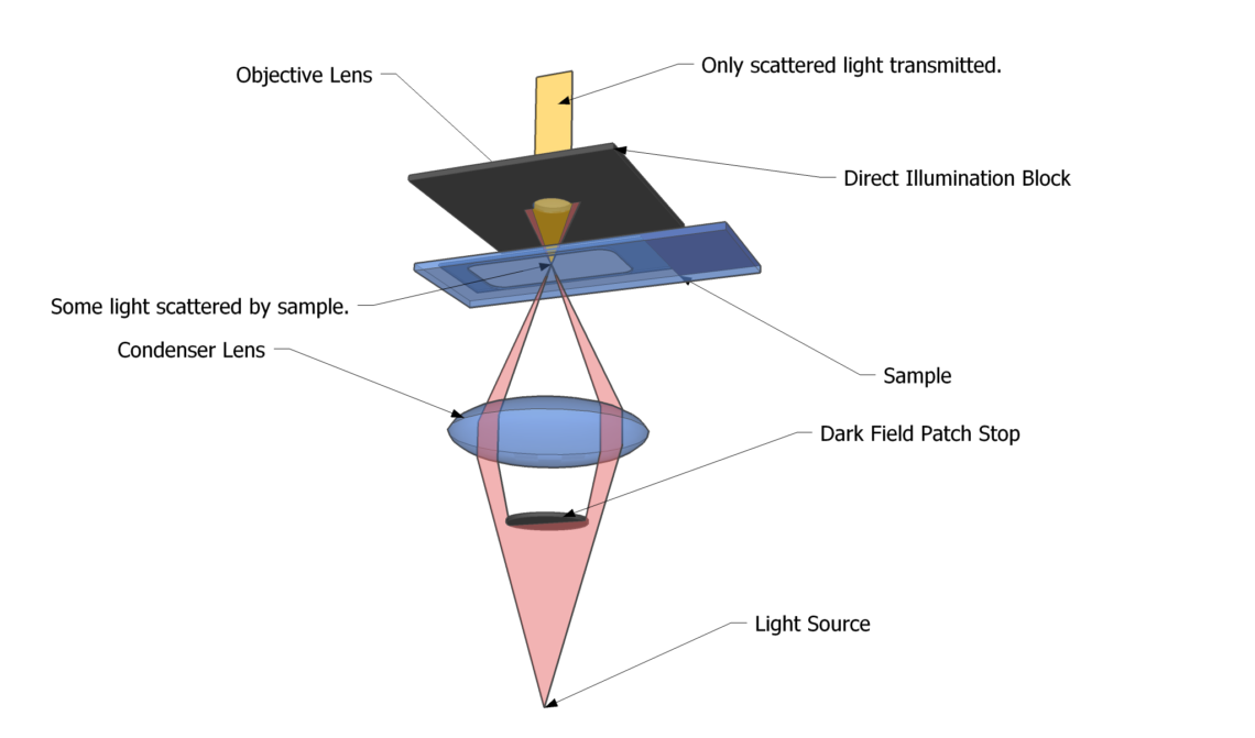
The solution splits into two directions. One is a physical solution: redesigning the illumination’s angle of incidence and how scattered light is collected, to match the target’s reflectivity characteristics. Dark-field illumination in particular fires light at a low angle so that reflected light from a normal flat surface never enters the lens, selectively capturing only the scattered light that a defect produces. The other is an algorithmic solution: introducing edge AI inference based on unsupervised feature matching, which can be trained without any defective samples, to identify anomalies using only normal data. This article covers both of these axes together with an actual optical-setup spec.
Why coaxial epi-illumination runs into limits on specular surfaces
Point. On a target with high specular reflectivity, dark-field illumination is often more favorable than coaxial epi-illumination for securing defect contrast.
Reason. Coaxial epi-illumination aligns the light source with the camera’s optical axis and fires light perpendicular to the target, which is a strength for obtaining uniform illuminance on a mirror-like surface with strong planar reflection. But precisely because the surface is smooth, the difference in reflection angle between the normal region and the defective region is small, so a shallow defect like a crack or micro-scratch gets captured at nearly the same brightness as the background, running into a contrast limit before it ever reaches a resolution limit.
Example. According to semiconductor wafer-inspection material published by Exosens in the first half of 2026, dark-field inspection plays a key role in revealing low-contrast edge defects and micro-particles in dense pattern layouts, and is being extended further by combining it with ultraviolet (UV) imaging to raise dark-field sensitivity another step. The same principle applies to automotive paint-surface inspection. A recently published lightweight detection network, SAR-YOLO (Stage-wise Attention Refinement), introduces a staged attention mechanism to detect small defects on heavily specular painted surfaces — and it, too, is designed on the premise of an input image with reflected light excluded as much as possible at the lighting stage.
Point. It is therefore reasonable to first confirm the target’s surface material and reflectivity, then consider dark-field illumination as the first choice for a target dominated by specular reflection, and coaxial epi-illumination or a low-angle ring light for a matte surface dominated by diffuse reflection. That said, reflectivity can vary subtly with the coating lot or the condition of the injection mold, so the premise that this cannot be confirmed before sample testing always has to be kept in mind.
Edge AI decision logic trained only on defect-free samples
Point. On a new line where defect samples are hard to obtain, an unsupervised feature-matching-based algorithm becomes a practical option when combined with dark-field illumination.
Reason. Defects on a specular surface vary widely in location and shape, so it takes a long time to gather a sufficiently large defect dataset. Learning the feature space from normal samples alone, and classifying at inference time any patch that deviates from the normal distribution as an anomaly, has the advantage of being applicable from the earliest stage of mass production. Running the deep-learning inference on an edge module rather than in the cloud on top of that makes it possible to keep the latency to an inspection decision within the line’s tact time.
Example. A recently published study on deflectometry-based classification of defects on specular surfaces proposed a structure that combines bright-field and dark-field illumination to obtain richer surface information, and detects defects through an unsupervised patch-matching network trained only on normal samples. On the edge-inference hardware side, as of 2026 the industrial-vision trend is for M.2-form-factor acceleration modules to settle in as the standard, with reports of achieving sub-100 ms latency at under 10 W power — enough to keep up with line speed without occupying separate host-system resources.
Point. That said, software image processing alone cannot fully cover the fundamental defects of a hardware optical setup (oversaturation, low-light noise, and the like). The algorithm’s role is, at most, to refine the defect signal on top of a well-designed lighting-and-lens combination, and an approach that only advances the algorithm while the lighting design itself is poor is not recommended.
Core framework matching table
Below is an example spec for a dark-field illumination setup for inspecting specular surfaces (a glossy injection-molded housing, PCB solder pads, and the like). In actual application, lens magnification and WD need to be re-tuned to match the target’s curvature and reflectivity variation.
| Category | Item | Spec |
|---|---|---|
| ① Minimum detectable defect size | Target defects | Micro-scratches, indentations, foreign matter |
| Minimum detectable size | 30 µm | |
| ② Optical setup | Lighting method | Dark-field (low-angle ring illumination, angle of incidence 10–15°) |
| Lens spec | Telecentric lens, 0.5× magnification, F6.5 | |
| WD (working distance) | 90 mm secured (including clearance for the lighting ring’s insertion space) | |
| Camera interface | GigE Vision (10 GigE) | |
| ③ Algorithm parameters | Input resolution | 2048 px × 2048 px |
| Detection method | Unsupervised patch feature matching (trained on normal samples) | |
| Inference location | Edge module (M.2 accelerator), target latency < 100 ms | |
| Decision threshold | Top-0.5% cutoff on anomaly score |
What this table shows is clear. To render a 30 µm-class micro-defect into contrast with dark-field illumination alone, low-angle incidence and a telecentric lens’s distortion suppression have to work together, and the 90 mm WD is a figure that accounts not only for the defect signal’s resolution but for the physical space needed to fit the lighting ring itself. The algorithm only performs at its best on top of the high-contrast input secured this way.
Comparative view: dark-field vs. coaxial epi-illumination, when the opposite choice is favorable
It’s true that dark-field illumination has an edge on shallow defects on specular surfaces, but it isn’t superior in every situation. When the target surface is a matte injection-molded part with uniform diffuse-reflection characteristics, or when the inspection target cares more about uniform illuminance across the whole surface — as in judging the presence of printed text or markings rather than a defect — coaxial epi-illumination actually produces more stable results. Also, on a target with significant curvature, dark-field’s low-angle lighting can create shadowed regions, opening up inspection blind spots, in which case combining it with dome illumination needs to be considered. Which lighting method is favorable depends on the actual target’s material, curvature, and coating condition, so the premise that this cannot be confirmed before sample testing is worth emphasizing once again.
Field Checkpoints
- WD (working distance) secured: confirm that the dark-field ring light and the lens barrel do not physically interfere, and that at least 90 mm of clearance is secured.
- Confirm that the target surface’s reflectivity has been measured in advance on a specular-vs-diffuse basis (including variation by coating lot).
- When using a telecentric lens, confirm that curvature variation across the target does not cause focus loss within the working range (depth of field).
- Confirm that the edge AI module’s inference latency has been benchmarked to be comfortably shorter than the actual line tact time.
- For an unsupervised model, re-confirm that the normal-sample data sufficiently reflects actual production variation (lot-to-lot variation, seasonal humidity changes, and the like).
References
- Exosens, “Wafer Inspection at Advanced Nodes” (2026)
- Research on SAR-YOLO, a Stage-wise Attention Refinement-based automotive paint-defect detection network, ScienceDirect
- Research on classification of specular-surface defects based on deflectometry and multimodal fusion, ScienceDirect
- Related patents: US8681328 (dark-field defect inspection method/apparatus), US6870949 (coaxial narrow-angle dark-field illumination), US10094787 (multi-surface specular reflection inspector), US10176588 / US10977814 (specular surface inspection system and method), US8228496 (defect inspection method and apparatus) — verify original text on Google Patents/USPTO


You May Also Like
Keeping Frame Rate and Lighting from Colliding on a High-Speed Inspection Line

Automotive Part Appearance Inspection: Lighting Design Comes First