The Surface You Could Only See at a Standstill — How Color-Multiplexed Strobing Breaks the Standstill Condition of Photometric Stereo
LIGHTING / ALGORITHM
A shallow dent on a matte-painted surface, a faint sink mark on an injection-molded part, a missing stroke in an engraved character. These defects have something in common. Their color and brightness are almost identical to a good part, and only the surface slope differs. A 2D image captured under a single light source produces no contrast at all.
Photometric stereo is the classic answer to this problem. Several images of the same field of view are captured while lights in different directions are switched on in sequence, and the per-pixel surface normal is recovered from the brightness variation. However, this method carries an old precondition — both the camera and the target must remain stationary during capture. If the target moves while N images are taken with changing illumination, pixel registration breaks down and the normal computation collapses with it.
Left unaddressed, the cost spreads across the entire inspection design. You end up choosing one of three paths: stopping the line (tact loss), restricting inspection to stop-and-go robot stations (throughput loss), or downgrading surface defect inspection to sampling (escape risk). In the end, photometric stereo has remained confined to laboratories and fixed equipment because of its operating conditions, not because of its performance.
The solution lies on the illumination side. If illumination direction is divided by wavelength instead of by time, information from multiple lighting directions can be packed into far fewer exposures.
The bottleneck in photometric stereo was never the computation — it was the time spent counting illumination directions.
1. Surface Material and Reflectance Come First
Point. A photometric stereo feasibility review must start with checking the reflection characteristics of the target surface, not with the camera.
Reason. The formulation of this technique rests on the assumption that the surface is close to Lambertian. That is, the observed luminance must be the same from any viewing direction and must depend only on the cosine of the angle between the illumination direction and the normal. When the specular component is strong, highlights saturate at certain illumination directions and the normal solution for those pixels converges to a physically wrong value. Machined metal surfaces with heavy diffuse reflection and high-gloss surfaces sit farthest from this assumption.
Example. A matte-painted injection-molded housing is a good target. Diffuse reflection dominates, so brightness variation with illumination direction carries the normal information almost intact. A mirror-polished metal cover, by contrast, is a bad target. In that case the physically correct approach is to solve for the slope from the reflected pattern using deflectometry, rather than solving for the normal from brightness.
Point. In other words, photometric stereo is not universal — it is a tool for surfaces dominated by diffuse reflection. Deployed without verifying reflectance characteristics, the resulting normal map looks plausible while being wrong.
2. Color Multiplexing — Carrying Direction on Wavelength
Point. If illumination direction is separated by wavelength rather than by time, the number of exposures drops and the standstill condition is relaxed.
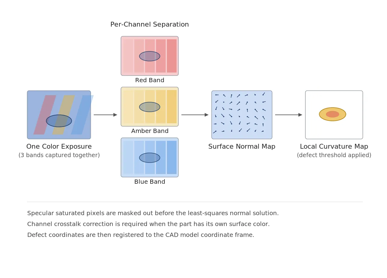
Reason. A color camera separates different wavelength bands simultaneously within a single exposure. If a different wavelength is assigned to each illumination direction, one color image becomes a bundle of several directional illumination images. This is the basic idea behind color multiplexing, or spectral multiplexing. The cost is clear — if the target itself has color, the wavelength dependence of the surface reflectance becomes mixed with the directional illumination information, and separating them requires additional assumptions or correction.
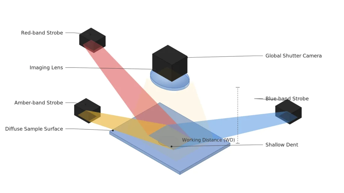
Example. In September 2026, PHOTODEX from AIT (Austrian Institute of Technology) was selected as one of the five finalists for the VISION Award 2026. Its full title is “PHOTODEX: Breaking the Motion Barrier in Photometric Stereo, Mobile Inspection System for Intelligent, Robust Industrial Surface Analysis”. According to the published description, it combines high-speed imaging with color-coded strobing illumination to acquire the required photometric information in two exposures placed very close together. This contrasts with conventional photometric stereo systems, which required both the camera and the target to be stationary and were therefore limited to laboratories, fixed equipment, and stop-and-go robot inspection.
Point. Reducing this to two exposures does not mean registration error has disappeared. It means the time interval that must be registered has shrunk to the gap between the two exposures. How many µm the target moves within that interval now becomes the new design specification.
3. Where to Put the Result — CAD Registration
Point. Inspection in motion is unusable unless it also records “where the image was taken”.
Reason. In a fixed-station inspection the coordinates are self-evident. The target arrives at a defined position, and the defect coordinate is simply the coordinate within the field of view (FOV). In handheld or robot-borne inspection, however, the viewpoint changes with every capture, so the point on the part that a defect coordinate corresponds to must be established separately. Without that step, neither repeatable re-inspection nor process root-cause tracing is possible.
Example. PHOTODEX describes registering detected defects to the CAD model, linking them to a digital twin, and generating spatially referenced data for AI-based quality assurance. In other words the deliverable is not a “list of defect images” but a “defect distribution in the part coordinate system”.
Point. The insight to take from this is as follows. The real value of photometric stereo in motion is not speed but the coordinate system. Process improvement only follows when defect history accumulates at the same point across repeated inspections of the same part — something a fixed station design provided for free, and something a moving inspection must implement explicitly.
A normal map captured on the move is just a pretty picture until it is attached to the part coordinate system.
4. Core Framework — Matching Table
| Category | Item | Specification / Parameter | Basis and Notes |
|---|---|---|---|
| ① Minimum Defect Size | Shallow dent on matte-painted surface | Diameter 300 µm, depth 5 µm or more | Design assumption. Detected via normal slope change |
| ① Minimum Defect Size | Sink mark on molded part | Diameter 500 µm or more | Design assumption. Targets gentle slope change |
| ① Minimum Defect Size | Missing stroke in engraved character | Line width 150 µm or more | Design assumption. Must occupy 3 px or more |
| ② Optical Setup | Illumination method | Wavelength-per-direction (color-coded) strobing, at least 3 directions | Three directions is the minimum for a 3-component normal solution |
| ② Optical Setup | Illumination layout | Elevation 25~35° from the optical axis, equally spaced azimuth | Design assumption. Lower elevation raises sensitivity to fine slopes |
| ② Optical Setup | Camera | Color global shutter, strobe-synchronized trigger | A rolling shutter introduces distortion when capturing in motion |
| ② Optical Setup | Lens | Focal length 25 mm, F/5.6 | Design assumption. Prioritizes depth of field (DOF) in motion |
| ② Optical Setup | WD (working distance) | 200 mm or more must be secured | Measured on the real setup, including interference between the multi-direction light ring and the handheld or robot end effector |
| ② Optical Setup | Magnification and FOV | FOV 100 mm × 75 mm, 50 µm/px | A 300 µm dent occupies 6 px |
| ② Optical Setup | Allowable displacement between exposures | Target displacement between the two exposures < 1 px (= 50 µm) | Upper bound on registration error. Derive the strobe interval backward from line speed |
| ③ Algorithm | Channel separation | Inverse-matrix separation of illumination direction per color channel plus crosstalk correction | Correction is required when the target has its own color |
| ③ Algorithm | Normal recovery | Least-squares solution of the Lambertian model | Specular saturated pixels are masked out |
| ③ Algorithm | Defect feature | Local curvature of the normal slope map | Threshold is applied to the slope map, not the brightness map |
| ③ Algorithm | Detection threshold | Curvature deviation > 3σ | σ is re-estimated from 30 good parts |
| ③ Algorithm | Coordinate registration | Transform defect coordinates into the CAD model coordinate system | Mandatory for inspection in motion |
What the table implies. The single line in ② — “target displacement between the two exposures < 1 px” — determines the entire practical specification of this system. Narrowing the FOV to raise resolution shrinks the allowable displacement to a few µm at the same line speed, which forces a tighter strobe interval, which in turn forces higher illumination peak power. Resolution, speed, and illumination power are bound together in one equation.
5. Related Patents (Verified as Existing)
| Patent Number | Title | Assignee | Priority Date / Status |
|---|---|---|---|
| US 9,773,304 B2 | Inspection apparatus, inspection method, and program | Keyence Corp. | 2014-06-09 / Active |
| US 8,717,578 B2 | Profilometer, measuring apparatus, and observing apparatus | Omron Corp. | 2009-04-10 / Active |
| US 9,396,544 B2 | Single image photometric stereo for colored objects | Adobe Inc. (original assignee Adobe Systems Inc.) | 2014-01-08 / Active |
| US 2012/0056994 A1 | Single-shot photometric stereo by spectral multiplexing | University of Southern California | 2010-08-30 / Abandoned |
Patents whose assignee could not be explicitly confirmed were excluded from the citation list. The last entry is an abandoned application that was never granted, but it still matters as prior art, since the idea of single-shot spectral multiplexing was already published in 2010.
6. Conditions Where the Opposite Approach Is Better
- High-gloss and mirror surfaces: The Lambertian assumption does not hold. Deflectometry, which reads the slope of the reflected pattern directly, is the physically correct choice.
- Targets with strong and varied intrinsic color: Color multiplexing mixes the illumination wavelength with the surface reflectance spectrum, so the classic approach of dividing direction by time (accepting the standstill condition) is more accurate.
- Defects already visible through color or brightness difference: Normal recovery only adds computational cost. Single-illumination 2D inspection is more economical.
- Cases requiring absolute height values: Photometric stereo yields normals (slopes), and height is obtained by integration, so low-frequency drift accumulates. Structured light or confocal methods are the better fit.
Surface reflection characteristics vary with the paint lot, the surface treatment, and aging, so this cannot be guaranteed before a sample test.
Field Note
The point I most often got wrong when first reviewing this method was reading “two exposures” as “the standstill condition is gone”. In practice the standstill condition has not disappeared; it has moved into the interval between the two exposures, and a new task appears: multiplying that interval by line speed and confirming it does not exceed 50 µm. On a continuously running strip line where the target never stops, this calculation pushes up both the strobe interval and the illumination peak power at once, and it repeatedly brought me back to the illumination power supply design. Layer the diffuse-reflection-dominant precondition on top of that, and for injection-molded housings whose paint lot changes it was safer to keep the qualifier cannot be guaranteed before a sample test attached all the way through.
Field Checkpoints
- Is a WD of 200 mm or more secured by actual measurement — verify with the multi-direction light ring, the end effector, and the handheld grip all included.
- Has it been confirmed on real parts that the target surface is diffuse-reflection dominant — a large specular fraction breaks the premise of this technique.
- Has the allowable displacement between the two exposures been derived backward from line speed — beyond 1 px the normal map blurs.
- Is the camera a global shutter — a rolling shutter creates geometric distortion when capturing in motion.
- Does the intrinsic color of the target conflict with the illumination wavelength assignment — if it does, design channel crosstalk correction separately.
- Is there a path to register defect coordinates into the part coordinate system — without it, history tracing is impossible in inspection on the move.
Related Developments (2026-09-15 to 09-22)
- AIT Austrian Institute of Technology, PHOTODEX selected as one of the five finalists for the VISION Award 2026. It combines high-speed imaging with color-coded strobing illumination to acquire photometric information in two closely spaced exposures, and registers detected defects to the CAD model.
- The same finalist group includes Lidwave Odem (4D coherent vision on a single silicon chip, per-pixel Doppler velocity), Medabsy (virtual design of machine vision systems and synthetic training data with pixel-level defect annotation), photonicSENS (single-sensor, single-exposure plenoptic 3D), and Singular Photonics (Litavis SPAD sensor).
- The award will be announced on 7 October 2026 at VISION 2026 in Stuttgart.

Noctvision
A machine vision engineer who fits cameras, lenses, lighting, and image-processing algorithms together for a living. Years spent on continuous production lines, vibration, heat, and dust included, working through diffuse reflection, contrast, and resolution differences too fine for a spec sheet to capture inform every post here, closing the gap between theory and the shop floor. Off duty, that same eye for light and lenses goes into repairing fully mechanical vintage film cameras.

You May Also Like
How to Handle Imaging on Highly Reflective Surfaces
Why Does a Black Spot Remain in the Center Under a Dome Light? — Solving Curved Specular Illumination with Viewing-Hole Geometry, Coaxial Fill Light, Dome Diameter and WD