What Optical Design Needs to Not Miss Defects on a High-Speed Line
When parts pass by at dozens per second on a production line, a surface defect on the order of tens of µm is hard to catch with a slow shutter. A long exposure time lets motion blur erase the contrast difference, and the defect flows straight through to shipment, coming back as rework and return costs. What matters isn’t camera performance — it’s an optical design that secures contrast within that brief instant.
I recently came across news, in the Korea Machine Vision Industry Association’s August newsletter, that Laonpeople’s golf-sensor business had already surpassed last year’s full-year results in first-half revenue alone. The optical design or business judgment behind a golf sensor is outside this writer’s scope and would need separate review, but the task of not losing a fast-moving target sits on the same underlying principles — high-speed shutter, trigger synchronization, high-frame-rate capture — that connect directly to high-speed inspection in industrial settings.
Surface material and reflectivity come first
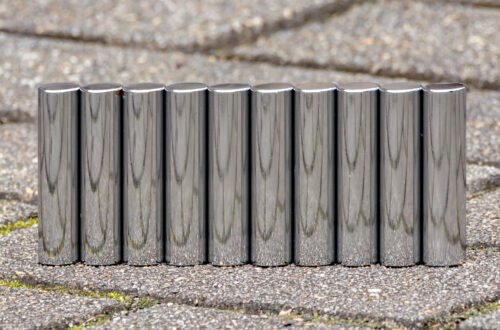
The first thing to look at in a high-speed inspection setup isn’t the camera spec — it’s surface material and reflectivity. Diffuse-reflection behavior and contrast both change with material. A matte PCB silkscreen surface is stable with coaxial illumination alone, but a high-gloss black injection-molded part shows heavy diffuse-reflection variation depending on angle, changing the result. This kind of material cannot be confirmed before sample testing.
What kills motion blur isn’t frame rate
When a target passes quickly, exposure time needs to be extremely short to avoid blur, but the shorter it gets, the less light there is, and contrast gets buried in noise. The solution isn’t frame rate — it’s strobe illumination that puts out a strong burst of light for an instant, combined with precise synchronization that aligns the flash timing to the trigger signal. Compress the flash duration down to tens of µs, and a defect gets rendered stably at a minimum of 3–5 px or more on screen.
Lens spec is set on the premise that WD is secured
Raise magnification to catch a µm-class defect, and focal length and WD (working distance) both shrink, creating interference with the lighting fixture. The lens spec has to be decided by calculating, together, both the resolution and FOV requirements and the WD needed to fit the lighting equipment and keep clearance from heat sources and vibration.
| Category | Detail item | Example spec |
|---|---|---|
| ① Minimum detectable defect size | Surface crack, pinhole, scratch | 40 µm |
| ② Optical setup | Lighting condition | High-output strobe, flash duration within 20 µs, instantaneous illuminance equivalent to roughly 50,000 lx or higher |
| Lens spec | 25 mm focal length, WD 100 mm secured, FOV 40×30 mm | |
| ③ Algorithm parameters | Trigger/synchronization | Trigger-delay variation within ±5 µs, frame-synchronization precision within 1 ms, defect rendered at a minimum of 3–5 px or more |
The spec above is only an example assuming a 40 µm defect on a matte material. Lighting wavelength, lens magnification, and trigger precision all need to be re-tuned depending on material reflectivity and line speed, and for a material with heavy diffuse-reflection variation, the spec cannot be finalized without sample testing.
Field Checkpoints
- Has the target surface’s material and reflectivity been identified in advance (matte/glossy, whether curved)?
- Does the WD (working distance) at the given lens magnification secure enough space for the lighting equipment and clearance from heat sources and vibration?
- Has the strobe illumination’s flash duration and trigger-synchronization precision been verified?
- Has actual sample testing been carried out for materials with heavy diffuse-reflection variation?
Without these four, even a sophisticated algorithm cannot cover an optical limitation through software alone.


You May Also Like
Adding Cameras to a Semiconductor/PCB Inspection Line: The Interface Rewrites the Optical Design
The Lens Comes Before the AI — Optical Setup Design for PCB Inspection