Highly Reflective Surface Defects: One Filtering Order Decides the Outcome — Bilateral Filters and the Division of Labor with Onboard AI Cameras
Introduction — The Moment a Filter Erases the Defect
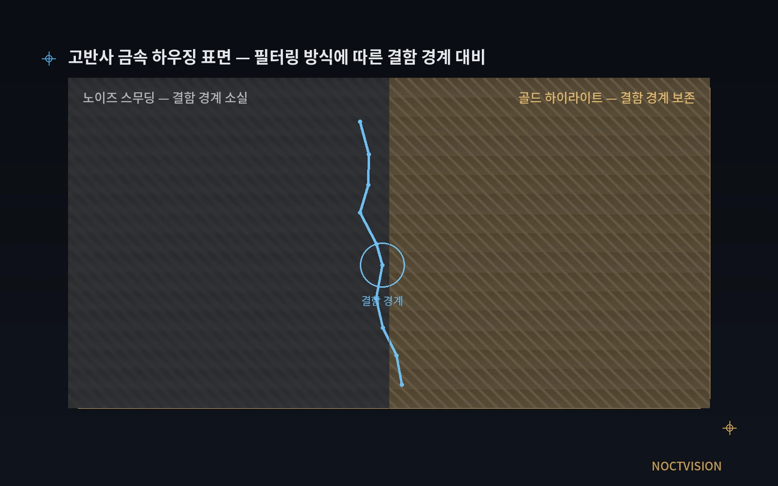
Inspecting highly reflective metal housings or glossy molded parts, you run into situations often where a single filtering step completely flips the result. Apply an ordinary smoothing filter straight onto a region saturated by specular highlights, and the defect boundary gets crushed right along with the noise, leading to a missed detection. Go the other way and raise sensitivity while leaving noise in place, and the boundary of a specular highlight gets classified as a defect, causing false detections to spike and the line to stop unnecessarily often. Leave either case unaddressed and it eventually comes back as downstream defect-leakage cost or lost productivity.
The solution is not to standardize on a single filter. Filter type needs to be applied differentially by defect type, with a deep-learning classification model layered on top, designed to match surface reflectivity. Recently emerging high-resolution sensors and embedded AI cameras are moving toward processing this entire pipeline in real time on the camera itself.
Body — The Chain Linking Reflectivity, Filtering, and the Classification Model
Before choosing a filter, the surface’s reflectivity characteristics have to be checked first. A surface with a strong specular component forms wide, locally saturated brightness regions, and these saturated regions tend to get crushed together with defect boundaries when passed through an ordinary Gaussian or median filter. Glossy molded housings, for example, often produce highlight-saturation regions with a brightness pattern similar to a defect, so saturation itself needs to be suppressed first through exposure and lighting conditions before filtering. This follows the same principle that hardware optical-setup defects cannot be fully covered by software image processing alone. Fix filter parameters without measuring reflectivity first, and you’ll need to re-tune every time the lot changes.
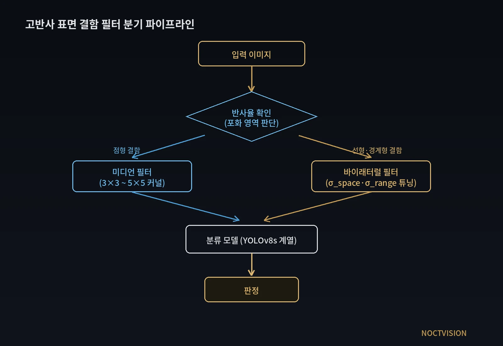
The optimal filter differs by defect type. A median filter is strong at removing salt-and-pepper-style noise such as foreign matter or point defects, but in the process of replacing pixels with the median of their neighborhood, defect boundaries can blur somewhat. A bilateral filter, by contrast, is the one classical smoothing filter that simultaneously satisfies both noise suppression and edge preservation, making it better suited to defects like cracks where a linear boundary is the core of the judgment. That said, a bilateral filter carries a relatively heavy computational load, so processing it within line takt time requires tuning its parameters (spatial standard deviation, value standard deviation) to a minimum matched to the defect size. In practice, a stable structure applies a median filter upstream on lines dominated by point defects, and a bilateral filter on lines where linear/boundary-type defects matter, branching between the two.
Published benchmark figures for deep-learning classification models should not be applied to the field as-is. A recently published improved-YOLOv8s-based surface-defect detection model reported impressive figures — an F1-score of 0.990 for fatigue-crack detection, 0.935 for linear cracks, and an overall mAP of 0.963. But these figures are benchmarks obtained under specific lighting and capture conditions, and as a recent review paper also points out, defect-detection research specialized for highly reflective metal surfaces has relatively less accumulated data compared to low-reflectivity materials. So when designing a filtering and classification pipeline for highly reflective surface defects, published benchmarks should be treated only as a reference, and re-validation against actual line data must always follow.
The trend of pushing filtering and inference down onto the camera itself is also worth watching. A structure that transmits frames to a separate PC before running filtering and inference sees transmission latency and data-volume burden grow as resolution climbs. Recently introduced embedded AI vision systems have adopted a structure that completes judgment right at the camera/line-controller stage without an external PC, and around the same time, a new GigE camera equipped with a 5.0MP-class BSI (back-side illuminated) sensor was also released — a trend of resolution and onboard processing capability rising together. Higher resolution means more pixels occupied by a single defect within the same field of view (FOV), so filter kernel size and a bilateral filter’s spatial standard deviation both need to be reconverted on a per-pixel basis. When designing the filter-classification pipeline, it’s advantageous to set the parameters of computationally heavy filters toward a lightweight direction from the start, keeping in mind the possibility of eventually moving this processing onboard.
Core Skeleton — Highly Reflective Surface Defect Filtering Parameter Matching Table
| Category | Item | Reference baseline |
|---|---|---|
| ① Minimum defect size to detect | Foreign matter on molded-housing surface | 40 µm |
| Hairline crack on metal part | 35 µm | |
| ② Optical setup | Lighting | Coaxial epi-illumination (bright-field) as baseline + low-angle dark-field as auxiliary |
| Lens | WD (working distance) must be secured in advance; effective resolution relative to FOV must be converted to pixels | |
| Sensor | Effective per-pixel detection limit re-calculated on a 5MP-class BSI sensor baseline | |
| ③ Algorithm parameters | Point-defect preprocessing | Median filter (kernel 3×3–5×5) |
| Linear-defect preprocessing | Bilateral filter (edge-preserving, σ_space/σ_range tuned per defect size) | |
| Classification model | YOLOv8s family; treat mAP benchmark as reference only | |
| Validation | Re-validation of published-dataset figures against in-house lot data is mandatory |
What this table implies is that, in filtering highly reflective surface defects, filter-type selection is a variable that governs detection rate no less than lens or lighting specs do. Unify the whole pipeline on a single filter without branching by defect type, and structural missed- or false-detections can recur repeatedly within specific defect classes.
A Comparative View — When a Median Filter Alone Is Enough
Not every line needs a bilateral filter. When defects are mostly localized and simple-boundary types like foreign matter or point-form smudges, the low-computation median filter alone can secure sufficient filtering performance for highly reflective surface defects. In this case, it can be advantageous to avoid the added compute and latency that adopting a bilateral filter entails, and instead choose a lightweight median-filter-based pipeline. That said, this judgment, too, is difficult to make without checking the actual defect-type distribution on a lot-by-lot basis, and cannot be confirmed before sample testing.
Field Checkpoints
- Has it been measured in advance that WD (working distance) doesn’t physically interfere with the lens/lighting layout?
- Has defect type (point/linear) been classified on a lot basis to set the criteria for applying median vs. bilateral filters?
- Has a procedure been put in place to re-validate published benchmark figures (F1, mAP, etc.) against in-house data?
- When sensor resolution changes, has filter kernel size and spatial standard deviation been reconverted on a per-pixel basis?
- Separate review needed — the target’s transport/alignment mechanism is outside the scope of this review.
References
- A Beginner’s Guide to Image Filtering in Machine Vision | UnitX
- An image processing technique for optimizing industrial defect detection using dehazing algorithms | PMC
- Parts Surface Defect Detection Algorithm Based on Improved YOLOv8s | Engineering Reports, Wiley
- A review of vision-based defect detection research for highly reflective metal surfaces | ScienceDirect
- Top 10 Machine Vision Companies & Technologies (2026) | Averroes
- UnitX Launches AI-Powered Smart Camera | Vision Systems Design
- Lens Aberrations | Field Curvature, Chromatic & More | Commonlands


You May Also Like
Where the μm Step Disappears: Measuring Both-Side Thickness Simultaneously with a Two-Channel Chromatic Confocal Controller

Machine-Vision Inspection: Physics Comes Before Software