A Machine Vision Lens Calculator That Catches the FOV Error a Shortcut Formula Misses
OPTICS
At a magnification of 0.14 the shortcut formula reports the FOV 14% too wide, and depth of field opened up at F8 runs into diffraction blur first.
With a lens calculator that takes sensor pixels, pixel size, FOV and object distance and returns focal length, resolution, depth of field and the Airy disk together, I followed the numbers of a 4,096 px setup one at a time.
About 14 min read
The first formula most people reach for when choosing a lens is f = sensor width × WD1 ÷ FOV2. One multiplication and one division give a focal length, so it works even in the middle of a quoting meeting. But the formula carries a condition: the magnification has to be small enough. A setup that views a 100 mm field with a 4,096 px wide sensor falls outside that condition, and the FOV the shortcut reports is about 14% wider than the real one.
Take the part as something like an injection-molded cover or a PCB about 100 mm across, a surface that scatters light fairly evenly. Even on a surface this well behaved, a wrong lens calculation only shows itself after the order is placed. You confirm a ‘13% FOV margin’ with the shortcut and order a 25 mm lens, then find after installation that at the same distance the field is about 1% narrower than the target and the edges of the part slide out of the frame. If the plan to stop down and widen the depth of field then runs into diffraction on small pixels as well, the lens and camera pairing, the mounting distance and the position of the light bracket all have to be decided again from the start.
So I write one line of the thin lens equation3 and attach two checks to it. One asks how many pixels the smallest defect covers, and the other finds the diameter of the diffraction blur from the aperture setting. The lens calculator below bundles these three formulas and compares seven standard focal lengths side by side at the same distance. Before opening it, I suggest following how the numbers connect.
The shortcut puts the sensor at the focal length
In a thin lens, the object distance u, image distance v and focal length f satisfy 1/f = 1/u + 1/v, and the magnification4 m is both v ÷ u and sensor width ÷ FOV. Solving the two together gives f = u × m ÷ (1 + m), and the sensor receives the image at a distance of f(1 + m) from the lens. The shortcut f = m × u assumes the sensor sits at the focal plane, where v = f. That is why dividing the shortcut value by the exact one always leaves 1 + m.
Thanks to this relationship, there is no separate error to memorize. The ratio by which the shortcut inflates the focal length is the magnification m itself. At a magnification of 0.064 it is 6.4%, at 0.141 it is 14.1%, and in high-magnification inspection that images the part at close to life size it grows toward a factor of two. For a wide field tens of times the sensor width the shortcut is nearly right, and the same formula misses by more as the magnification rises.
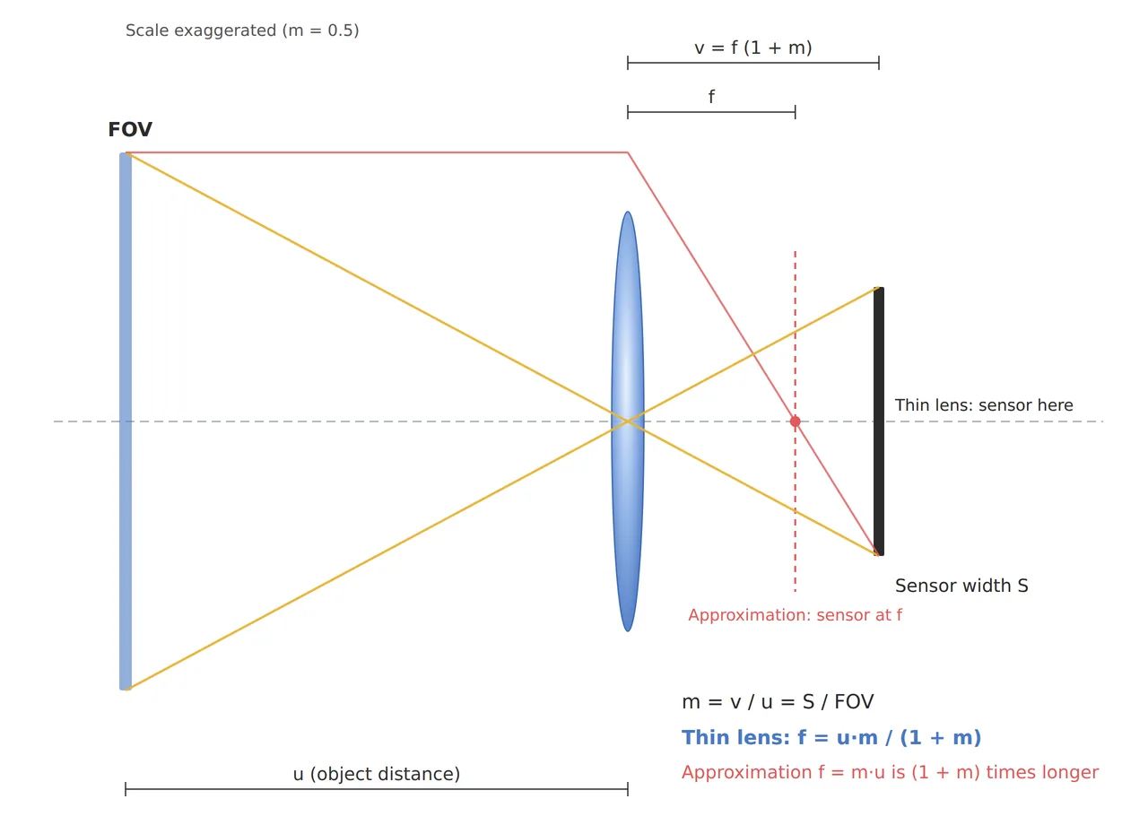
In the figure, watch the gap on the right between the red dashed line, where the shortcut puts the sensor, and the black bar, where the thin lens puts it. Viewing a 100 mm FOV at an object distance of 200 mm with a 1,600 px sensor of 4.0 μm pixels (6.4 mm wide) gives a magnification of 0.064, and the thin lens equation asks for a focal length of 12.03 mm. The shortcut returns 12.8 mm and leaves you torn between 12 mm and 16 mm, but once the calculation is corrected, 12 mm is very nearly the answer. The real FOV of that 12 mm lens, though, is 100.3 mm, barely over the target. Calculated with the shortcut, it comes out at 106.7 mm and looks as if there were more than 6% to spare. Once the magnification passes 0.05, I keep the shortcut value in a reference column only.
More pixels make the shortcut miss by more
The 1,600 px setup cannot be used even with the right focal length. The object-side pixel resolution5 is set by FOV ÷ horizontal pixel count, and 100 mm ÷ 1,600 px is 62.5 μm/px. A 100 μm defect covers only 1.6 pixels. My rule is that the smallest defect must cover at least three pixels. This setup is out at the sensor stage, before any lens is chosen. Filling three pixels takes a resolution of 33.3 μm/px or finer, which means at least 3,000 px across.
Switch to a 4,096 px sensor with 3.45 μm pixels (14.13 mm wide), and the resolution becomes 24.4 μm/px, with the 100 μm defect covering about 4.1 pixels. The margin comes at a price: the magnification rises to 0.141, and the shortcut’s error rises with it to 14.1%. The moment resolution goes up, the shortcut misses by more. Place a 25 mm lens at an object distance of 200 mm, and the shortcut shows a 113.0 mm FOV while the thin lens equation gives 98.9 mm, short of the target. Reaching 100 mm takes stretching the object distance to about 202 mm, and applying the shortcut again at that point inflates the FOV to 114.2 mm. That 2 mm is what the shortcut hides.
14.2%
How much the shortcut inflates the FOV of a 25 mm lens at a 202 mm object distance
4.1px
Pixels covered by a 100 μm defect on the 4,096 px sensor
202mm
Object distance at which a 25 mm lens gives a 100 mm FOV (thin lens)
Set the three numbers side by side, and the order of calculation shows. Resolution comes from the smallest defect, pixel count from resolution, magnification from pixel count and FOV, and the focal length comes last, from that magnification and the object distance. Pick the focal length first, and you end up spinning in place, trying to fix a resolution shortfall by swapping lenses. For a setup with magnification above 0.1, I would not lock in a lens with the shortcut; I back-calculate the FOV with the thin lens equation and check it once more against the lens maker’s FOV and WD table.
Stopping down grows blur before depth
When part heights vary, the next hand goes to the aperture. In close-up imaging, the total depth of field6 is calculated as DOF ≈ 2 × N × c × (1 + m) ÷ m². N is the f-number and c is the circle of confusion7, and the formula assumes the entrance and exit pupils of the lens are the same size (pupil magnification 1). Double the f-number and the depth of field doubles, so on paper stopping down always looks like a gain.
Light does not move that way. With magnification, the f-number the sensor actually sees grows to the working f-number8 Nw = N(1 + m), and the diameter of the Airy disk9 produced by diffraction is about 2.44 × λ × Nw. The depth-of-field formula counts only geometric blur, so once the Airy disk grows larger than c, the blur budget is already spent even at the point of perfect focus. The depth shown on the calculator stays the same, while the range that is actually sharp becomes narrower.
Assume the 4,096 px sensor, a 25 mm lens, an object distance of 202 mm (magnification 0.141) and 520 nm illumination, and put in the numbers. Take c as one pixel (3.45 μm) at F8, and the depth of field comes out at about 3.15 mm. At that setting, though, the Airy disk is about 11.6 μm, 3.4 pixels, over three times c. The 3.15 mm stays a number on paper. Widen c to two pixels (6.9 μm) and use F4, and the depth of field is the same 3.15 mm while the Airy disk, about 5.79 μm (1.7 pixels), fits inside c.
Double the f-number
and the depth of field doubles, so it seems height variation can simply be covered with the aperture.
Add the Airy disk to the calculation
the 3.15 mm at F8 with a one-pixel c collapses because the 11.6 μm blur is over three times c, and only F4 with a two-pixel c keeps the same 3.15 mm.
The two cards part ways on whether the number holds. Both read 3.15 mm, but one comes from inside the blur budget and the other from a budget already overspent. Widening c to two pixels, however, requires the smallest defect to cover its pixels with that much room. Here it covers about 4.1, so it tolerates two pixels of blur, but in a setup where the defect barely exceeds three pixels, c is tied to one pixel and the f-number is tied low too. If part height variation exceeds this depth of field, I check how fixture height is controlled before raising the f-number any further, and if that is still not enough, I look at optical alternatives such as a telecentric lens10 or a variable-focus lens. The telecentric side is calculated separately in the article on telecentric lenses and depth of field.
Two setups in the calculator
The lens calculator below takes eight inputs: sensor horizontal pixels, pixel size, target FOV, object distance u, f-number, circle of confusion c (in pixels), illumination wavelength and minimum defect size. Change a value, and the results table and the comparison table for seven standard focal lengths (8, 12, 16, 25, 35, 50 and 75 mm) recalculate at once, judged on two criteria: whether the FOV meets the target and whether the smallest defect covers three pixels or more. The defaults are the example from the focal length calculation article: 1,600 px, 4.0 μm pixels, a 100 mm FOV and a 200 mm object distance.
Leave the defaults as they are, and not one row in the comparison table reads ‘OK’, while two warnings appear below the results: one that the defect covers 1.6 pixels, short of three, and one that at F8 the Airy disk of about 10.8 μm is larger than a one-pixel c (4.0 μm). To my eye, this default screen is the most useful view in the calculator. The conclusion that the sensor has to change first comes out of a single table. The 12 mm row matches the field with a 100.3 mm FOV but is flagged ‘under 3 px’, and the rows with longer focal lengths enlarge the defect at the cost of FOV. Enter the second setup (4,096 px, 3.45 μm, 100 mm FOV, 202 mm, F4, c of 2 px), and every warning disappears and only the 25 mm row turns to OK. The 35 mm row enlarges the defect to 6.1 pixels but shrinks the FOV to 67.4 mm and drops out.
The calculation runs only inside the browser. The inputs are sent nowhere. One thing to watch is that u is measured from the lens principal plane11. The real WD from the lens front to the part differs from u by the position of that plane, and the difference changes with each lens design, so it can only be confirmed from the maker’s data. Narrow the candidates with the calculator, then make the final check against the FOV and WD table and the minimum object distance in the lens spec sheet.
Three lines for the spec sheet
The numbers have to move into spec-sheet sentences before someone else can rebuild the same setup. Here the setup that catches a 100 μm defect with the 4,096 px sensor and a 25 mm lens is reduced to three lines, with only the optical line split into lens, distance and depth.
| Item | Value | Condition · basis | In plain words |
|---|---|---|---|
| ① Minimum defect size | 100 μm = about 4.1 px | 100 ÷ 24.4 at 24.4 μm/px. Three pixels or more is the condition for detection | One defect covers a little over four pixels |
| ② Sensor · lens | 4,096 px, 3.45 μm pixels, 25 mm at F4 | Thin-lens focal length required: 25.01 mm (u 202 mm) | A 25 mm lens on a sensor 14.13 mm wide |
| ② WD · FOV | Object distance u about 202 mm, FOV 100.0 mm | Real WD fixed from the lens front with the maker’s data and checked with the light mounting space added. The shortcut FOV of 114.2 mm is about 14% too wide | The lens principal plane sits about 202 mm above the part |
| ② Depth · diffraction | DOF about 3.15 mm, Airy disk 5.79 μm (1.7 px) | c of 2 px = 6.9 μm, λ 520 nm assumed, Nw 4.57 | The depth where blur stays within two pixels is a little over 3 mm front to back |
| ③ Algorithm parameters | Size filter: long side of 4 px or more | Integer floor of the 4.1 px in ①. Valid only while blur stays within the two-pixel c | Specks smaller than four pixels are not counted as defects |
Read the table from top to bottom, and the first thing that shows is that the moment 4,096 px buys margin for the defect, the magnification rises to 0.141 and the shortcut’s FOV overstatement widens to 14%. In this setup, a choice that leans on the shortcut produces a shortfall that looks like margin. For the same 3.15 mm depth of field, the F8 pairing with a one-pixel c collapses under diffraction and only F4 with a two-pixel c survives. Resolution and magnification, depth and diffraction are bound in one line, so changing a single cell moves the whole table. I would pin this table to the front of a lens quotation. It makes the basis column get read before the lens name.
There are places where this method does not fit. For dimensional measurement or parts with large height variation, choosing a telecentric lens, whose magnification stays nearly constant, beats polishing the calculation for a regular lens whose magnification changes with distance. A wide-field setup whose field exceeds 100 times the sensor width has a magnification below 0.01, so the shortcut’s error stays under 1% and the shortcut is enough. Zoom lenses and extension rings, which move the principal plane with every setting, are faster and more accurate to handle by shooting a grid chart and measuring the magnification. Even with every calculation right, how much defect contrast a glossy surface will give cannot be guaranteed before a sample test.
The thin lens and Airy disk calculations are worth working once by hand for anyone preparing to become a vision engineer. When the calculator’s numbers match the hand calculation, a lens catalog reads differently. From the side that sets the equipment budget, the bracket rebuilt and the light repositioned because of a wrong lens cost more than the lens itself. Why the physics comes first is written out at length in the physics-first article. This article explains technology and is not investment advice. See our Disclaimer.
Field Note
If a spec sheet arrives with a lens chosen by the shortcut, I recalculate the FOV with the thin lens equation once more before the order goes out. At a magnification around 0.14 the left and right of the frame can come out narrower than the target, and making up that difference with mounting distance shifts it by a few millimeters, as with the 202 mm here, which moves the light bracket position too. In the review sheet I keep separate columns for the thin-lens FOV and the Airy disk diameter, and only pairings that pass both stay on the lens list. Last, I look at whether the minimum object distance in the lens spec sheet is shorter than the calculated u.
Field Checkpoints
To turn the review sheet from the field note into spec-sheet sentences, answer the questions below in order.
- Is the WD measured from the lens front secured without hitting the light or the fixture? (the calculator’s u is from the principal plane, so recheck with the maker’s FOV and WD table)
- With magnification m above 0.1, was the FOV kept away from the shortcut? (above it, the shortcut FOV comes out more than 10% too wide)
- Does the smallest defect cover three pixels or more? (minimum defect ÷ pixel resolution)
- Does part height variation fit inside the calculated depth of field, and is the Airy disk smaller than the circle of confusion c? (if the blur exceeds c, the depth figure does not hold)
- Does the lens image circle cover the sensor, and is the calculated distance longer than the lens minimum object distance? (check the lens spec sheet)
- For a glossy surface, has defect contrast been checked with boundary samples? (the calculation does not promise contrast)
Frequently Asked Questions
When is the shortcut good enough?
Since the ratio by which the shortcut inflates the focal length equals the magnification m, deciding the error you can accept gives the answer. If you need to stay within 1%, the shortcut is enough only at magnification 0.01 or below, a wide field at least 100 times the sensor width. For a sensor 14.13 mm wide, that means a field wider than 1,413 mm.
How many pixels should the circle of confusion c be?
There is no single answer; it is set by how much room the smallest defect has in its pixels. If the defect barely exceeds three pixels, the blur allowance has to stay tight, around one pixel, and if it covers four or more, up to two pixels can be considered. Either way, check in the same table whether the Airy disk diameter is smaller than c.
Why does the WD in a lens spec sheet differ from the calculator’s u?
The calculator treats the lens as a single sheet with no thickness and measures distance from the principal plane. A real lens lines up several glass elements over a length of tens of millimeters, so the principal plane does not sit where the lens front is. That is why, for the same setup, the WD in a spec sheet is written differently from u, and since the difference varies by lens, it is fixed only with the maker’s data.
Glossary
- [1] WD working distance
The distance from the front of the lens to the surface being inspected. The calculator’s object distance u is measured from the principal plane, so it differs from WD lens by lens. ↩ - [2] FOV field of view
The width and height of the inspected surface captured in one frame. With the same sensor it widens or narrows with the lens and the distance. ↩ - [3] Thin lens equation 1/f = 1/u + 1/v
An equation that treats the lens as a sheet with no thickness and writes the relation of focal length, object distance and image distance as 1/f = 1/u + 1/v. It is the same equation that tells how far a magnifying glass focuses sunlight. ↩ - [4] Magnification m
The size of the image on the sensor divided by the real object size. At 0.141, 100 mm on the object forms 14.1 mm on the sensor. ↩ - [5] Pixel resolution μm/px
The length on the inspected surface that one pixel covers. At 24.4 μm/px, each pixel is responsible for 24.4 μm of the part. ↩ - [6] Depth of field DOF
The range of depth that stays sharp in front of and behind the focus distance. Raising the f-number widens it, but diffraction grows with it. ↩ - [7] Circle of confusion c
The diameter up to which a point blurred by defocus is still treated as sharp. The text sets it at one or two pixels. ↩ - [8] Working f-number Nw
The f-number the sensor side actually experiences when shooting with magnification, approximated by multiplying the marked f-number by (1 + m). It explains why a lens gets darker the closer it shoots. ↩ - [9] Airy disk Airy disk
The disk a point of light spreads into as it diffracts through the aperture. Its diameter is about 2.44 × wavelength × f-number, so it grows as the aperture is stopped down. ↩ - [10] Telecentric lens telecentric lens
A lens whose magnification barely changes when the object moves back and forth within a set range. Used for dimensional measurement and for parts at different heights. ↩ - [11] Principal plane principal plane
The reference plane from which distances are measured when a thick lens is calculated as a single thin lens. In a real lens it sits somewhere other than the front, so it is checked in the spec sheet. ↩
References
- Derivation of the Macro Depth of Field Equation (coinimaging.com): DOF = 2·c·N·(m + 1)/m², pupil magnification 1 assumed
- Edmund Optics, System Throughput, f/#, and Numerical Aperture: (f/#)w ≈ (1 + m) × f/#
- Edmund Optics, The Airy Disk and Diffraction Limit: Airy disk diameter ≈ 2.44 × λ × f/#
- Formulas: 1/f = 1/u + 1/v, m = sensor width ÷ FOV, f = u × m ÷ (1 + m), shortcut f = m × u, pixel resolution = FOV ÷ horizontal pixels, Nw = N(1 + m). Assumptions: 520 nm wavelength, pupil magnification 1, thin-lens approximation
Related reading — How to Calculate Machine-Vision Lens Focal Length · When Height Varies, F7.1 Beats F16 on a Telecentric Lens · In Machine-Vision Inspection, Physics Comes Before Software

Noctvision
An engineer who has handled mechanical design and project management for production equipment since 2005. Here I work through the cameras, lenses and lighting that go into equipment with formulas and public data, and record the assumptions and sources alongside the numbers.


You May Also Like
How 3D Structured Light Measures a Solder Lead Lift That Brightness Cannot Show
Why Do Shiny Parts Look Cold to a Thermal Camera?