Building a Vision Inspection App with PySide6 and OpenCV — A Minimal UI for Tuning Defect Detection Parameters on Screen (Full Code)
ALGORITHM / PYTHON
Defect detection algorithms are usually born in a script on a laptop or in a Jupyter cell. Numbers such as a threshold of 25 or a kernel of 31 px are buried in the middle of the code, and the result is checked in a single window that shows the image. That is enough at a developer’s desk, but not next to the line.
Changing a parameter means opening the code, so adjustment on site stops until a developer arrives, and nothing records who judged what with which values, so when over-detection or missed detection comes back there is no way to trace the cause. An inspection system that cannot be adjusted ends up running with a loosened threshold, and the smallest defects slip through that gap first.
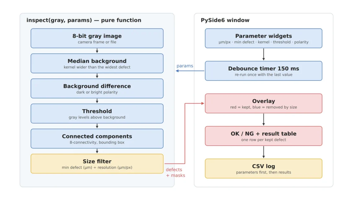
The fix is not a large inspection package but a minimal UI that separates the inspection logic into a pure function and adds only parameter inputs, a result overlay, a verdict and a CSV log on top. This article builds that skeleton in about 220 lines of PySide6 and OpenCV and walks through three design points together with a screen captured from an actual run.
The purpose of an inspection UI is not to decorate the screen but to keep the parameters used for a verdict together with the result.
1. Separate Logic from UI — The Pure Function inspect()
Point. Keep the inspection logic in a pure function that takes an image and parameters and returns only results, not inside a UI class.
Reason. If logic is mixed into the UI, the same verdict cannot be reproduced in a batch re-inspection or a unit test, and changing the UI framework means rewriting the algorithm too. Once it is a function, you can first verify without any window that the same input gives the same output.
Example. The example inspect() (a) estimates the background (illumination shading) with a median blur whose kernel is larger than the defects, (b) takes the background difference according to defect polarity, (c) binarizes with a gray-level threshold, and (d) applies a minimum-length filter after 8-connected component labeling. The minimum length is converted as minimum defect [µm] ÷ pixel resolution [µm/px], and 60 µm ÷ 20 µm/px = 3 px. On the synthetic test image this function kept two defects, a scratch and a spot, and removed with the size filter one speck of only 2 × 2 px that had passed the threshold.
Point. Taking the parameters in µm rather than px is the key. When the lens or FOV changes, updating the single resolution value keeps the defect criterion unchanged.
2. The Window — Parameters, Overlay, Verdict, Record
Point. The window holds only the five inputs the algorithm actually uses (resolution, minimum defect, background kernel, threshold, polarity), the verdict, the result table and CSV saving.
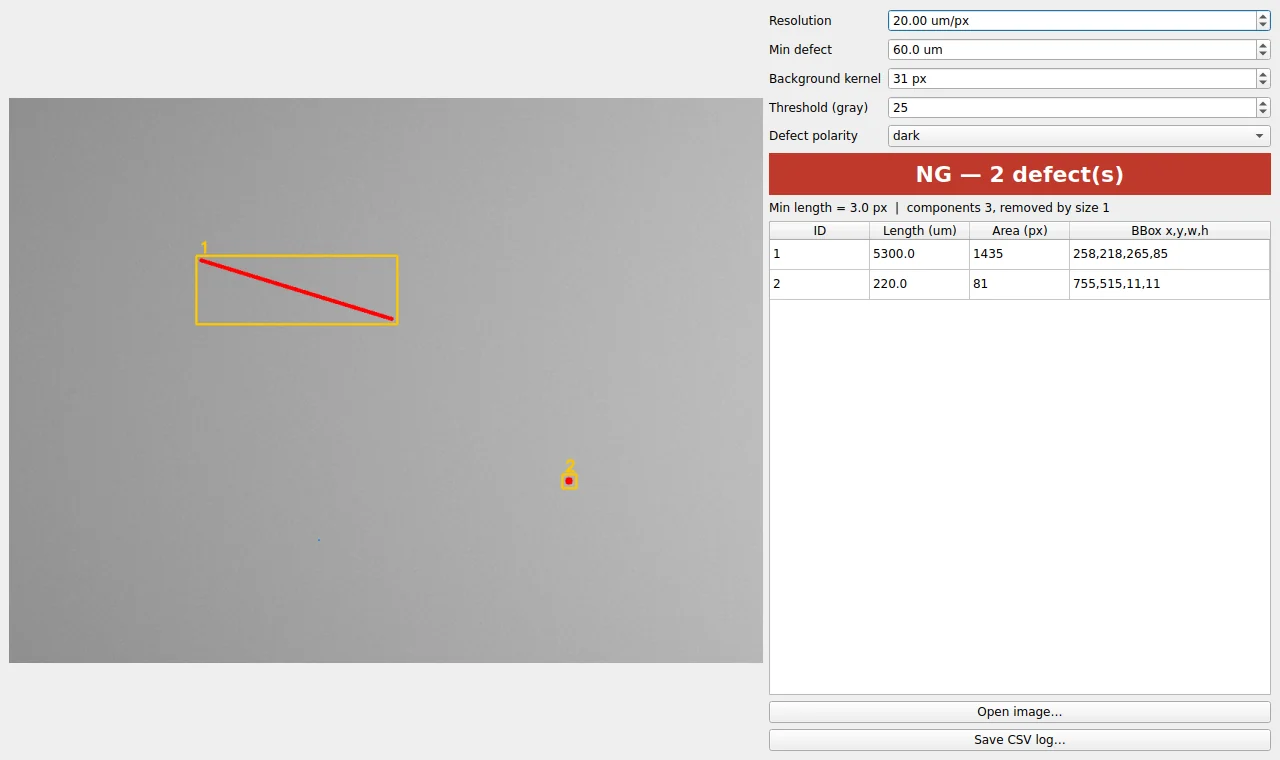
Reason. Limiting the inputs to algorithm parameters makes the values on screen correspond one-to-one with the cause of a verdict. Conversely, the more options on screen that the algorithm does not use, the harder it becomes to trace what changed when the results differ.
Example. Re-inspecting on every turn of a spin box also inspects every intermediate value passed along the way. The example gathers inputs with a 150 ms single-shot timer (debounce) and inspects only once with the last value. Here, connecting a spin box’s valueChanged(int) straight to QTimer.start passes the value as the start(msec) argument and changes the debounce interval itself. In practice, setting the threshold to 40 changed the interval from 150 ms to 40 ms, and the example prevents this by connecting through a lambda that drops the argument. The overlay paints kept defects red and components that passed the threshold but were removed by the size filter blue, so the screen distinguishes “removed because it is small” from “not seen”. A line under the verdict shows the minimum length in px and the number of components removed by the size filter, and the CSV writes one parameter line before the result rows.
Point. Only when the basis of a verdict stays on the screen and in the file can you start from “what was the threshold at that time” when over-detection or missed detection comes back.
3. numpy → QImage Conversion — The Image Skews When the Width Is Not a Multiple of 4
Point. Always pass bytesPerLine (bytes per row) when handing a numpy array to QImage.
Reason. According to the Qt documentation, the constructor that does not take bytesPerLine assumes the scanline data is at least 32-bit aligned. If the width of an 8-bit gray image is not a multiple of 4, the numpy row pitch and the row pitch Qt assumes disagree, every row is shifted by a few bytes and the image skews diagonally. QImage also references the buffer instead of copying it, so the buffer must stay valid while the QImage is alive.
![QImage conversion comparison in which the same 8-bit image skews diagonally and defect shapes change without bytesPerLine but displays correctly with strides[0]](https://noctvision.com/wp-content/uploads/2026/09/noctvision-pyside6-opencv-vision-inspection-gui-03.webp)
Example. Converting a 1021 px wide image without bytesPerLine makes Qt read 1024 bytes per row, shifting each row by 3 bytes. In the actual reproduction (figure above), the scratch whose bounding box is 265 px wide turned into a steep bar 37 px wide, the spot 11 px in diameter turned into a slanted streak 31 px wide, and the bottom 3 rows showed a black band where bytes outside the original image were read (for the reproduction, the end of the buffer was padded with zeros so no memory outside the range was read). Because defect length and position change, it is not only the display that is wrong; every measurement computed from display coordinates goes off. The example to_qimage() passes img.strides[0] as bytesPerLine and cuts the dependency on the numpy buffer with .copy().
Point. ROI crops from camera SDKs often produce images of arbitrary width. It is safer to verify the conversion path by deliberately using a test image whose width is not a multiple of 4.
4. Core Framework — Matching Table
| Category | Item | Spec / Parameter | Basis / Note |
|---|---|---|---|
| ① Minimum defect size | Minimum defect length | 60 µm | Example assumption. 3 px at 20 µm/px |
| ② Optical setup | Input image | 8-bit gray, synthetic test image 1024 × 768 px | In real use the lighting and lens setup must be fixed first |
| ② Optical setup | Pixel resolution | 20 µm/px (FOV about 20.5 mm assumed) | 1024 px × 20 µm = 20.48 mm |
| ② Optical setup | WD (working distance) | Not covered because the example reads image files — a real setup must confirm the WD is secured | Back-calculate distance and focal length in the lens calculator article |
| ③ Algorithm | Background estimate | Median blur 31 px | Odd kernel larger than the widest defect (spot 11 px) |
| ③ Algorithm | Background difference / threshold | Polarity dark, threshold 25 gray levels | About 8 times the synthetic noise sigma of 3 gray levels |
| ③ Algorithm | Connected components / size filter | 8-connectivity, bounding box long side ≥ 3 px | 60 µm ÷ 20 µm/px |
| ③ Algorithm | UI re-inspection | Debounce 150 ms | One inspection with the last value after rapid input |
Table insight. The detection floor of this example is set by two values together: the size filter (3 px) and the threshold (25 gray levels). On the synthetic image, raising the threshold to 90 gray levels left 0 defects, and lowering the minimum defect to 20 µm (1 px) detected 3, including the speck that had been removed. In other words, changing those two values in the UI is changing the defect criterion, which is why the parameters must be recorded with the results.
5. Full Code and Setup
- Create a virtual environment:
python -m venv .venv, then activate it (macOS and Linuxsource .venv/bin/activate, Windows.venv\Scripts\activate) - Install packages:
pip install PySide6 opencv-python-headless numpy— install only the headless OpenCV package. The PyPI page also states that multiple OpenCV packages should not be installed in the same environment. - Run:
python nv_inspect_ui.py(synthetic test image) orpython nv_inspect_ui.py part.png
# -*- coding: utf-8 -*-
"""
nv_inspect_ui.py — minimal PySide6 + OpenCV vision inspection UI (example)

Environment
  - Python 3.10 or later, a virtual environment (venv) is recommended
      python -m venv .venv && source .venv/bin/activate   (Windows: .venv\\Scripts\\activate)
      pip install PySide6 opencv-python-headless numpy
  - Install only one OpenCV package: the headless one.
    (do not install opencv-python and opencv-python-headless in the same environment)

Usage
  python nv_inspect_ui.py              # start with the synthetic test image
  python nv_inspect_ui.py part.png     # start with a saved inspection image (8-bit gray/color)
"""
import csv
import sys
from dataclasses import dataclass

import cv2
import numpy as np
from PySide6.QtCore import Qt, QTimer
from PySide6.QtGui import QImage, QPixmap
from PySide6.QtWidgets import (
    QApplication, QComboBox, QDoubleSpinBox, QFileDialog, QFormLayout, QHBoxLayout,
    QLabel, QMainWindow, QPushButton, QSpinBox, QTableWidget, QTableWidgetItem,
    QVBoxLayout, QWidget,
)


# ---------------------------------------------------------------------------
# 1) Inspection parameters — one-to-one with the input widgets
# ---------------------------------------------------------------------------
@dataclass
class InspectParams:
    um_per_px: float = 20.0      # pixel resolution [um/px] = FOV[mm] x 1000 / horizontal pixels
    min_defect_um: float = 60.0  # minimum defect length to detect [um]
    bg_kernel_px: int = 31       # background kernel [px] — must be wider than the widest defect, or the defect is absorbed into the background
    threshold: int = 25          # threshold on difference from background [gray levels, 0-255]
    polarity: str = "dark"       # "dark": defects darker than background, "bright": brighter


# ---------------------------------------------------------------------------
# 2) Inspection logic — a pure function separate from the UI (reusable in unit tests and batch runs)
# ---------------------------------------------------------------------------
def inspect(gray: np.ndarray, p: InspectParams):
    """Inspect one gray image and return (defect list, threshold mask, kept mask)."""
    # (a) Background estimate: median blur with a kernel larger than the defect -> keeps only illumination shading
    k = max(3, p.bg_kernel_px | 1)                 # kernel must be odd
    background = cv2.medianBlur(gray, k)

    # (b) Background difference: keep only how far each pixel departs from the background, by polarity
    if p.polarity == "dark":
        diff = cv2.subtract(background, gray)      # saturating subtraction (negative -> 0)
    else:
        diff = cv2.subtract(gray, background)

    # (c) Threshold
    _, mask = cv2.threshold(diff, p.threshold, 255, cv2.THRESH_BINARY)

    # (d) Connected component labeling (8-connectivity) + size filter
    #     minimum length [px] = minimum defect [um] / resolution [um/px]
    #     e.g. 60 um / 20 um/px = 3 px -> shorter components are discarded as noise
    min_len_px = p.min_defect_um / p.um_per_px
    n, labels, stats, _ = cv2.connectedComponentsWithStats(mask, connectivity=8)
    defects = []
    kept = np.zeros_like(mask)                      # mask of components that pass the size filter
    for i in range(1, n):                           # label 0 is the background
        x, y, w, h, area = stats[i]
        length_px = max(w, h)                       # long side of the bounding box as the length
        if length_px < min_len_px:
            continue                                # above threshold but smaller than the minimum defect -> removed
        kept[labels == i] = 255
        defects.append({
            "id": len(defects) + 1,
            "x": int(x), "y": int(y), "w": int(w), "h": int(h),
            "area_px": int(area),
            "length_um": round(float(length_px * p.um_per_px), 1),   # px -> um
        })
    return defects, mask, kept


# ---------------------------------------------------------------------------
# 3) numpy -> QImage conversion — always pass the stride (bytesPerLine)
# ---------------------------------------------------------------------------
def to_qimage(img: np.ndarray) -> QImage:
    img = np.ascontiguousarray(img)
    h, w = img.shape[:2]
    if img.ndim == 2:
        qimg = QImage(img.data, w, h, img.strides[0], QImage.Format_Grayscale8)
    else:
        rgb = cv2.cvtColor(img, cv2.COLOR_BGR2RGB)
        qimg = QImage(rgb.data, w, h, rgb.strides[0], QImage.Format_RGB888)
    # QImage references the numpy buffer without copying -> return a copy, since the buffer may be freed after the function returns
    return qimg.copy()


def make_test_image(w=1024, h=768, seed=7) -> np.ndarray:
    """Synthetic test image: shading + noise + one scratch + one spot + one speck under 3 px."""
    rng = np.random.default_rng(seed)
    yy, xx = np.mgrid[0:h, 0:w]
    img = 150 + 40 * (xx / w) - 25 * ((yy - h / 2) / h) ** 2      # illumination shading, brighter to the right
    img = img + rng.normal(0, 3.0, (h, w))                        # sensor noise (sigma = 3 gray levels)
    img = np.clip(img, 0, 255).astype(np.uint8)
    cv2.line(img, (260, 220), (520, 300), 105, 3)                 # scratch: 3 px wide
    cv2.circle(img, (760, 520), 5, 95, -1)                        # spot: about 11 px in diameter
    img[600:602, 420:422] = 110                                   # speck: 2 x 2 px (under 3 px) -> must be removed by the size filter
    return img


# ---------------------------------------------------------------------------
# 4) Main window — re-inspect 150 ms after a parameter change (debounce)
# ---------------------------------------------------------------------------
class MainWindow(QMainWindow):
    def __init__(self, gray: np.ndarray):
        super().__init__()
        self.setWindowTitle("Minimal Vision Inspection — PySide6 + OpenCV")
        self.gray = gray
        self.defects = []

        # image view
        self.view = QLabel(alignment=Qt.AlignCenter)
        self.view.setMinimumSize(640, 480)

        # parameter inputs
        self.sp_res = QDoubleSpinBox(decimals=2, minimum=0.5, maximum=500.0, value=20.0, suffix=" um/px")
        self.sp_min = QDoubleSpinBox(decimals=1, minimum=1.0, maximum=5000.0, value=60.0, suffix=" um")
        self.sp_ker = QSpinBox(minimum=3, maximum=151, singleStep=2, value=31, suffix=" px")
        self.sp_thr = QSpinBox(minimum=1, maximum=255, value=25)
        self.cb_pol = QComboBox(); self.cb_pol.addItems(["dark", "bright"])
        form = QFormLayout()
        form.addRow("Resolution", self.sp_res)
        form.addRow("Min defect", self.sp_min)
        form.addRow("Background kernel", self.sp_ker)
        form.addRow("Threshold (gray)", self.sp_thr)
        form.addRow("Defect polarity", self.cb_pol)

        # verdict, result table, buttons
        self.lb_judge = QLabel(alignment=Qt.AlignCenter)
        self.lb_judge.setStyleSheet("font-size:22px;font-weight:bold;padding:8px;")
        self.lb_info = QLabel()                     # shows the minimum length [px] and how many components the size filter removed
        self.table = QTableWidget(0, 4)
        self.table.setHorizontalHeaderLabels(["ID", "Length (um)", "Area (px)", "BBox x,y,w,h"])
        self.table.horizontalHeader().setStretchLastSection(True)
        self.table.verticalHeader().setVisible(False)
        bt_open = QPushButton("Open image…"); bt_open.clicked.connect(self.open_image)
        bt_csv = QPushButton("Save CSV log…"); bt_csv.clicked.connect(self.save_csv)

        side = QVBoxLayout()
        side.addLayout(form); side.addWidget(self.lb_judge); side.addWidget(self.lb_info); side.addWidget(self.table)
        side.addWidget(bt_open); side.addWidget(bt_csv)
        root = QHBoxLayout(); root.addWidget(self.view, 3); root.addLayout(side, 2)
        central = QWidget(); central.setLayout(root); self.setCentralWidget(central)

        # debounce timer: however fast the spin boxes change, inspect once with the last value
        self.timer = QTimer(self, singleShot=True, interval=150)
        self.timer.timeout.connect(self.run)
        # note: connecting valueChanged(int) straight to timer.start passes the value as start(msec)
        #       and changes the debounce interval -> connect through a lambda that drops the argument
        for w in (self.sp_res, self.sp_min, self.sp_ker, self.sp_thr):
            w.valueChanged.connect(lambda *_: self.timer.start())
        self.cb_pol.currentIndexChanged.connect(lambda *_: self.timer.start())
        self.run()

    def params(self) -> InspectParams:
        return InspectParams(self.sp_res.value(), self.sp_min.value(),
                             self.sp_ker.value(), self.sp_thr.value(), self.cb_pol.currentText())

    def run(self):
        p = self.params()
        self.defects, mask, kept = inspect(self.gray, p)
        # overlay: kept defect pixels red, pixels above threshold but removed by size blue, bounding boxes yellow
        vis = cv2.cvtColor(self.gray, cv2.COLOR_GRAY2BGR)
        vis[(mask > 0) & (kept == 0)] = (255, 120, 0)
        vis[kept > 0] = (0, 0, 255)
        n_all = cv2.connectedComponents(mask, connectivity=8)[0] - 1
        self.lb_info.setText(f"Min length = {p.min_defect_um / p.um_per_px:.1f} px  |  "
                             f"components {n_all}, removed by size {n_all - len(self.defects)}")
        for d in self.defects:
            cv2.rectangle(vis, (d["x"] - 4, d["y"] - 4), (d["x"] + d["w"] + 4, d["y"] + d["h"] + 4), (0, 200, 255), 2)
            cv2.putText(vis, str(d["id"]), (d["x"], d["y"] - 8), cv2.FONT_HERSHEY_SIMPLEX, 0.7, (0, 200, 255), 2)
        pix = QPixmap.fromImage(to_qimage(vis))
        self.view.setPixmap(pix.scaled(self.view.size(), Qt.KeepAspectRatio, Qt.SmoothTransformation))
        # verdict: NG if at least one defect is kept
        ng = len(self.defects) > 0
        self.lb_judge.setText(f"NG — {len(self.defects)} defect(s)" if ng else "OK")
        self.lb_judge.setStyleSheet("font-size:22px;font-weight:bold;padding:8px;color:#fff;"
                                    + ("background:#c0392b;" if ng else "background:#2e7d32;"))
        self.table.setRowCount(len(self.defects))
        for r, d in enumerate(self.defects):
            for c, v in enumerate([d["id"], d["length_um"], d["area_px"], f'{d["x"]},{d["y"]},{d["w"]},{d["h"]}']):
                self.table.setItem(r, c, QTableWidgetItem(str(v)))

    def resizeEvent(self, e):
        super().resizeEvent(e)
        self.timer.start()   # refit the display scale when the window is resized

    def open_image(self):
        path, _ = QFileDialog.getOpenFileName(self, "Open image", "", "Images (*.png *.bmp *.tif *.jpg)")
        if path:
            img = cv2.imread(path, cv2.IMREAD_GRAYSCALE)
            if img is not None:
                self.gray = img
                self.run()

    def save_csv(self):
        path, _ = QFileDialog.getSaveFileName(self, "Save CSV log", "defects.csv", "CSV (*.csv)")
        if not path:
            return
        p = self.params()
        with open(path, "w", newline="", encoding="utf-8") as f:
            wr = csv.writer(f)
            # keeping the parameters with the results is what makes a verdict reproducible later
            wr.writerow(["um_per_px", p.um_per_px, "min_defect_um", p.min_defect_um,
                         "bg_kernel_px", p.bg_kernel_px, "threshold", p.threshold, "polarity", p.polarity])
            wr.writerow(["id", "length_um", "area_px", "x", "y", "w", "h"])
            for d in self.defects:
                wr.writerow([d["id"], d["length_um"], d["area_px"], d["x"], d["y"], d["w"], d["h"]])


if __name__ == "__main__":
    app = QApplication(sys.argv)
    src = cv2.imread(sys.argv[1], cv2.IMREAD_GRAYSCALE) if len(sys.argv) > 1 else None
    win = MainWindow(src if src is not None else make_test_image())
    win.resize(1280, 760)
    win.show()
    sys.exit(app.exec())
Test environment: Python 3.11, PySide6 6.11.2, OpenCV 4.13.0, numpy 2.4.4. The screen above was captured by running in Linux offscreen mode, and the logic was checked without a window in separate tests (two defects kept, speck removed, matching pixel values after converting a 1021 px wide image, a single re-inspection after rapid input, and the 150 ms debounce interval preserved).
6. Conditions Where the Opposite Approach Wins
- When the verdict logic is a deep learning model: the UI skeleton is the same, but what to record becomes the model version and input preprocessing conditions rather than thresholds (deep learning vs. rule-based article).
- Multiple cameras and short cycle times: running inspection in the GUI thread makes screen updates and inspection block each other. Move inspection to a separate thread or process and leave the UI only to display results.
- Inspection platforms that already manage parameter history: using that feature is better for change tracking than a separate UI.
Background kernel and threshold change with the diffuse reflection and shading of real images, so whether the example values can be used as they are cannot be guaranteed before a sample test.
Frequently Asked Questions
Q. Is there a reason to use PySide6 instead of PyQt?
The code in this example is almost identical in both bindings. PySide6 was chosen because it is the official Python binding provided by the Qt project itself, which makes it easy to line up documentation and versions with Qt. Distribution terms (licensing) have to be checked separately against the user’s own policy.
Q. How do I connect a real camera image?
inspect() only takes an 8-bit gray numpy array, so convert the frame from the camera SDK to the same format and pass it in. Real-time acquisition, however, needs a structure that receives frames in a separate thread and passes only the latest frame to the UI.
Field Note
Back when I tuned by editing a script’s threshold on a laptop next to the line, the same defect came back a few days later and nobody could remember which values had been used that day. Since then I hand a tool to the site only after making sure the values changed on screen are written to the first line of the result file. Once the parameters were recorded, it became possible to tell whether over-detection came from a change on the lighting side or from a threshold change. I always add, though, that a minimal UI like this is only an adjustment tool and cannot make up for contrast that the lighting and lens did not create.
Field Checkpoints
- Is the WD secured? — first confirm that the WD of the camera and lens producing the images for this UI is secured, including the lighting installation space.
- Does the resolution input (µm/px) match the real FOV ÷ pixel count — update this value first whenever the lens or distance changes.
- Is the background kernel larger than the widest defect (if smaller, large defects are absorbed into the background)?
- Were display coordinates and pixel values verified with an image whose width is not a multiple of 4?
- Are the parameters recorded in the CSV together with the results?
- For diffusely reflecting surfaces, threshold and kernel cannot be guaranteed before a sample test — were they tuned with limit samples?
References
- Qt 6 documentation — QImage — buffer validity, 32-bit alignment assumed by the constructor without bytesPerLine
- Qt for Python (PySide6) | Official Python Bindings — the official Qt Python binding
- PyPI — opencv-python-headless — “SELECT ONLY ONE OF THEM”, no GUI functionality
- OpenCV documentation — Structural Analysis and Shape Descriptors — connectedComponentsWithStats
Related reading — Deep Learning vs. Rule-Based Algorithms: When to Use Which · Machine-Vision Inspection: Physics Comes Before Software · Highly Reflective Surface Defects: One Filtering Order Decides the Outcome — Bilateral Filters and the Division of Labor with Onboard AI Cameras

Noctvision
A machine vision engineer who fits cameras, lenses, lighting, and image-processing algorithms together for a living. Years spent on continuous production lines, vibration, heat, and dust included, working through diffuse reflection, contrast, and resolution differences too fine for a spec sheet to capture inform every post here, closing the gap between theory and the shop floor. Off duty, that same eye for light and lenses goes into repairing fully mechanical vintage film cameras.


You May Also Like
What You Must Check Before Applying INT8 Quantization to Edge AI Inference: Why Micro-Defects Quietly Disappear
Is It Safe When the Average Latency Fits the Deadline? — Breaking Down the Edge Vision Inspection Latency Budget by p99