Why Do Shiny Parts Look Cold to a Thermal Camera?
OPTICS
What a thermal camera measures is the amount of infrared light that lands in one pixel.
When that pixel is wider than the part, or the part’s surface is as shiny as a mirror, the number on the screen mixes in the temperature of something other than the part.
About 16 min read
Pour the same boiling water into a stainless steel pot and a ceramic mug, point a thermal camera at both, and the two containers tell different temperatures on the screen. If the water is at 90 °C and the camera keeps a setting meant for a surface painted black, the math puts the side of the mug at a little over 88 °C, while the shiny side of the pot stays around 38 °C. The water in both is the same temperature. What differs is how much light each surface sends out on its own, and how much of its surroundings it reflects instead.
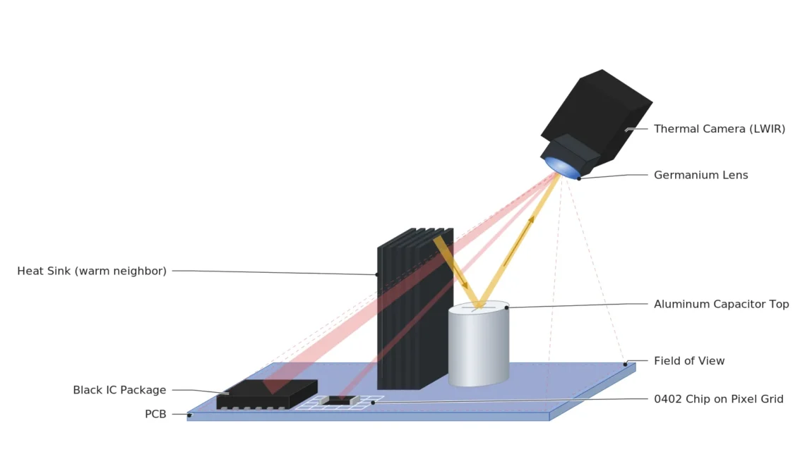
The same thing happens on a powered electronic board at a test station. On September 22, AT Sensors introduced the IRSX-2, a thermal camera that handles temperature measurement, evaluation and communication inside a single unit, and named thermal inspection of electronic components as one of its uses. Looking down at a powered board, a black IC reads close to its real temperature, but the top of an aluminum capacitor and a tiny 0402 chip1 tend to read colder than they are. If the camera also sounds the alarm by itself, what that number actually measured decides the whole verdict.
Trust that number as it is and draw an alarm line, and the cost comes from both directions. An overheated chip carries a lukewarm number into the box of passed parts, while a capacitor reflecting the heat of a nearby heat sink sends a perfectly good board to the rework shelf. Before touching the alarm line, I would measure two things. One is the area a pixel covers on the part; the other is the share of that pixel’s light that the part emitted itself.
Light at 10 μm, outside human vision
The light a thermal camera receives is long-wave infrared (LWIR)2. Objects at room temperature give off this light on their own, but its wavelength is around 10 μm3, far outside the 0.38 to 0.75 μm band the human eye can sense. Using Wien’s displacement law4, the wavelength an object at 25 °C emits most strongly is 9.72 μm, and for a 90 °C chip it is 7.98 μm. Ordinary glass blocks this band, so thermal camera lenses are made from materials such as germanium that let this light through.
Even at the same temperature, surfaces send out different amounts of light. Emissivity5 is the ratio against an ideal object that emits the most in theory, set to 1. In the emissivity table from IRISS, black electrical tape sits at 0.95 to 0.96 and a printed circuit board at about 0.91, while polished aluminum stops at 0.04 to 0.06 and polished stainless steel at 0.14 to 0.16. For an opaque surface, the share it emits and the share of surrounding light it reflects add up to 1. Aluminum with an emissivity of 0.05 sends back 95% of the long-wave infrared arriving from its surroundings.
So the light arriving at one pixel of the camera comes by two routes. One is light the part emits at its own temperature; the other is light from a warm object nearby that bends off the part’s surface into the lens.
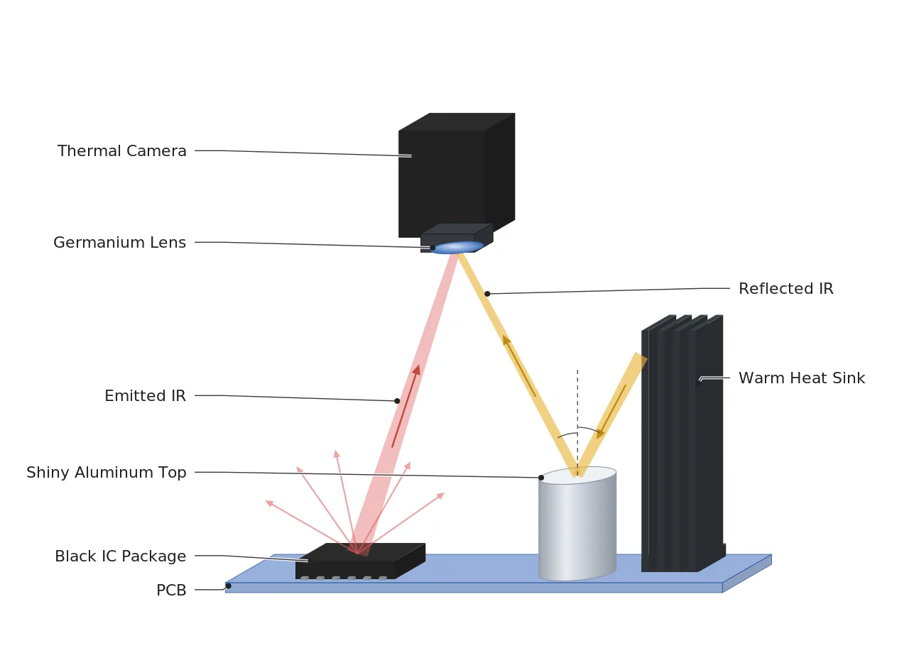
From the black IC on the left of the diagram, the first route is almost everything, while on the aluminum top on the right the second route takes up most of it. The camera cannot separate the two; it receives only their sum and turns it into a temperature. When I read a single number, my eye goes first to what surrounds that pixel. Only by knowing what stands next to it can the number be traced to its owner.
How much of the board one thermal pixel covers
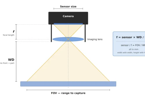
Of the two, the area comes first. The angle one pixel of a thermal camera opens toward the object is called the instantaneous field of view (IFOV)6, and it is the pixel pitch divided by the focal length. Pick 9.2 mm from the three focal lengths offered for the IRSX-2, 4.9, 9.2 and 13.6 mm, take a pixel pitch of 12 μm, and the IFOV is 1.30 mrad. With a distance from the lens to the part, the WD7, of 300 mm, one pixel covers 391 μm square on the board, and the whole image spans 250 × 200 mm. Both the pixel pitch and the distance are assumptions for the calculation.
An 0402 chip is 1.0 mm long and 0.5 mm wide. In this setup it spans 2.56 pixels one way and 1.28 pixels the other, so across its width it barely exceeds one pixel. Optris, a thermal camera maker, explains that to read temperature accurately the target must cover 3 × 3 or 4 × 4 pixels, and calls this area, which collects 90% of the target’s energy, the measurement field of view (MFOV)8. The measurement field of view in this setup is 1,174 μm, more than twice the short side of the 0402 chip.
The reason three pixels are needed lies in the lens. Light passing through a lens does not gather into a single point; it spreads into a small circle called the Airy disk9. Its diameter is 2.44 × wavelength × f-number, so with a wavelength of 10 μm and an f-number of 1.0 it comes to 24.4 μm, the width of two pixels. Traced back onto the board, that is a circle about 0.8 mm across, so even with a perfect lens the light from a 0.5 mm wide chip spills into neighboring pixels and the light of the surrounding board fills the gap.
One pixel of a thermal camera is in the same position as that thermometer. If the chip does not fill the pixel, the board fills the rest, and the camera writes down the mixed amount of light as a single temperature. Only when a hot spot covers three pixels in each direction do I call that number the part’s temperature. Anything narrower, and the number on screen is closer to an average of the part and the board.
A 90 °C chip that reads as 75 °C
How much mixing happens only shows once it is put into numbers. Say the chip has heated up to 90 °C and the surrounding board is at 45 °C, with both emissivities and the camera setting at 0.95. If the chip sits exactly across a pixel boundary, its 0.5 mm width splits into 0.25 mm in each of two pixels, and even the pixel holding the most chip is only 64% filled by it. Integrating the light in that pixel over the 8 to 14 μm band and converting it back to temperature gives this.
391μm
Width one pixel covers with a 9.2 mm lens at 300 mm
64%
Share of the most-filled pixel when the chip straddles a boundary
75°C
What the 90 °C chip shows on screen
If the alarm line were set at 85 °C, this chip would pass without a defect call. By the same calculation, the chip has to fill at least 87% of a pixel to trip the alarm, which only happens when it lines up luckily with the pixel grid. Add the blur of the lens and the displayed temperature drops further still. The direction is clear. If it were my setup, I would shrink the pixel before lowering the alarm line.
Photographers in the film era hit a similar wall. Many light meters built into cameras measured by averaging a wide area, so reading the brightness of a single backlit face on its own was hard. That is why some people carried a separate spot meter that measured only a narrow angle of about 1°. On a thermal camera, what plays the role of that spot meter is a short distance and a long focal length.
Switch to the 13.6 mm lens and pull the WD in to 180 mm, and one pixel shrinks to 159 μm, so the short side of the 0402 chip covers 3.15 pixels. The size problem is solved this way, with distance and lens. A shiny part is a different story: however close the camera gets, the number does not return to where it belongs.
The neighbor’s temperature in an aluminum top
The top of an aluminum electrolytic capacitor often shows bare metal. In the IRISS table, aluminum emissivity depends on the finish, 0.04 to 0.06 when polished, about 0.18 when roughened and 0.20 to 0.30 when oxidized, and here it is set in between at 0.10. With the capacitor heated to 70 °C, the surroundings at 25 °C and the camera left at the 0.95 setting meant for the board, the screen shows 30.6 °C. That is nearly 40 °C lower than the real temperature.
A low-emissivity surface is close to a mirror at this wavelength. Just as nobody calls a mirror hot because a candle shows in it, most of the light the shiny aluminum top hands to the camera comes from its surroundings. If a 60 °C heat sink stands at an angle nearby and its light, reflected off the top by specular reflection10, enters the camera, the same capacitor reads 62.7 °C. The part’s temperature has not changed; what pushed the number up by more than 30 °C is the heat sink next door.
Put emissivity on the horizontal axis and plot the temperature shown on screen, and the difference between the two cases becomes clear at a glance.
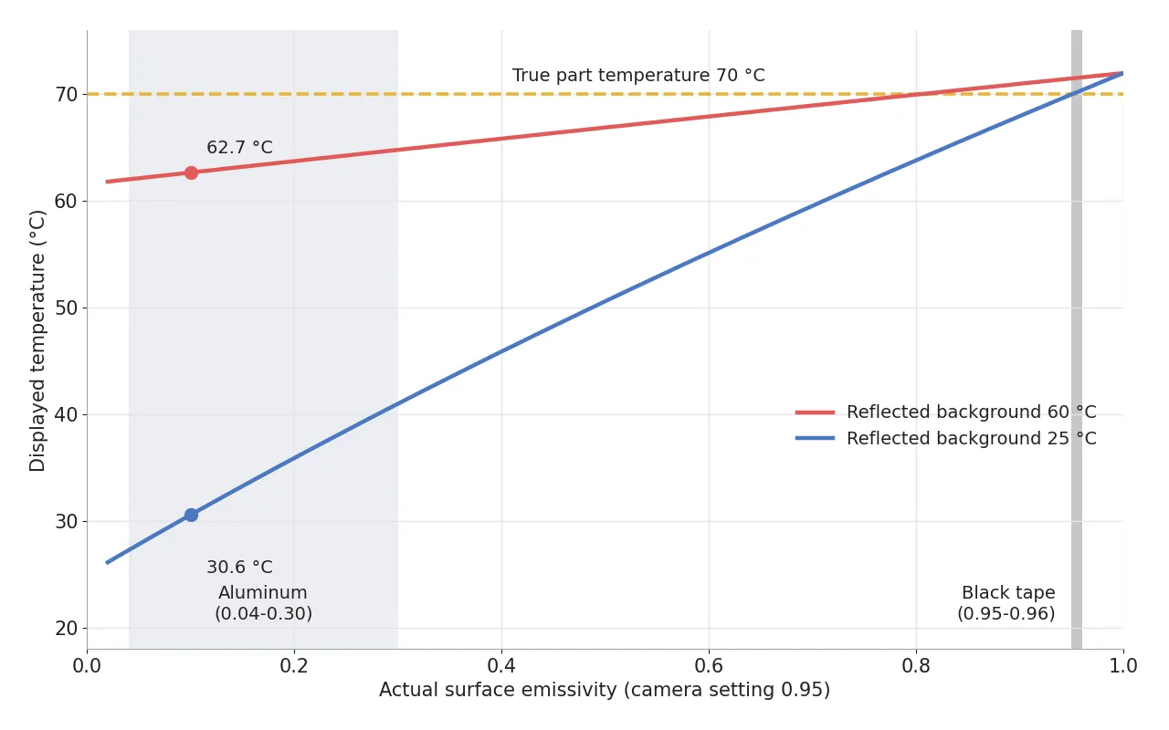
At the right end, where emissivity approaches 1, both lines gather near the true temperature of 70 °C; toward the left, the blue line is pulled toward the 25 °C surroundings and the red line toward the 60 °C heat sink. In the shaded aluminum range, the number resembles the surroundings more than the part. Enter an emissivity of 0.10 and a reflected apparent temperature11 of 25 °C correctly, and 70.0 °C does come back.
I do not trust that recovered number easily. On a surface with an emissivity of 0.10, every 1 °C error in the reflected apparent temperature moves the displayed temperature by 6.5 °C, and if the real emissivity is 0.12 but 0.10 is entered, the result is 77.5 °C. The same 1 °C error on a surface with an emissivity of 0.95 amounts to only 0.04 °C. On a metal top whose emissivity changes with oxidation and scratches, whether this number can serve as a pass criterion cannot be guaranteed before a sample test.
The check I recommend is simple. Move the camera sideways by a hand’s width. If the hot spot stays put on the part, it is the part’s heat; if it slides across the top along with the camera, it is a reflection. The guidance in the IRISS emissivity table describes the same check.
Distance and emissivity to fix before powering the board
Put the two calculations into a specification and they become a single table. The top row holds the smallest hot spot to catch, and below it come the optical setup that covers that spot with more than three pixels and the judgment conditions that deal with different emissivities by surface. Filled in with the assumptions so far, it looks like this.
| Item | Value | Condition and basis | In plain words |
|---|---|---|---|
| ① Minimum defect size | Hot spot at least 500 μm wide (short side of an 0402 chip) | To fill a 3 × 3 pixel measurement field of view, one pixel must be 167 μm or less. With a 13.6 mm lens, WD within 189 mm (pixel pitch of 12 μm assumed) | A part 0.5 mm wide must cover three pixels in each direction |
| ② Optical setup | 640 × 512 thermal camera, focal length 13.6 mm, WD 180 mm (whether it can be secured needs checking against the lens minimum focus distance), matte black hood | One pixel 159 μm, measurement field of view about 476 μm, image 102 × 81 mm. Blur circle on the board about 0.32 mm across (F1.0 and 10 μm wavelength assumed) | Move in close to the part, and block whatever could reflect in it with black walls |
| ③ Algorithm parameters | Emissivity 0.95 (black resin and board areas); metal tops left out of judgment areas and judged on the vinyl sleeve or an emissivity marker; reflected apparent temperature = hood temperature; judgment value = maximum of 3 × 3 pixel averages; alarm line 85 °C (assumed) | On a 0.10 emissivity surface, a 1 °C error in reflected temperature grows into a 6.5 °C error in displayed temperature | Read numbers only where they can be trusted, and never judge on a single spiking pixel |
The line at 189 mm is the center of gravity of this table. The WD has to come inside that distance for the 0402 chip to cover three pixels, and whether the lens can focus at that distance remains unknown until its minimum focus distance is checked. The image narrows to 102 × 81 mm, so a setup that captured a whole board in one frame turns into one that shoots it region by region. By my standard, the second row of the table stays a draft until these two points are confirmed.
The reflection side has to be solved through the structure of the station. It is safer to replace whatever could reflect in the part with black walls of known temperature, and to take low-emissivity spots such as metal tops out of the places where numbers are read.
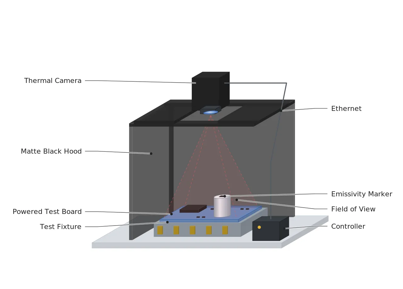
In the diagram, the matte black hood around the camera fixes the background that reflects in the parts to a single surface of known temperature, and the emissivity marker on the capacitor top creates a place to read instead of the metal. The procedure for measuring and compensating for reflected temperature is set out in ASTM E1862, and the one for emissivity in ASTM E1933. Methods that assign emissivity surface by surface have been around for a long time, like a patent (CN103196564B) that splits the image by material to build an emissivity map, but that map also holds only as long as the surface stays the same.
Where the camera also sounds the alarm
The more measurement and judgment merge into one camera, the larger the share of the person who sets the distance, lens and emissivity ahead of it. That person is a machine vision engineer who builds inspection equipment, or a technician who specializes in thermographic diagnosis, and in machine condition monitoring there is a personnel qualification standard for thermography, ISO 18436-7, divided into three categories. To anyone entering this field, I recommend getting two calculations into your hands first. One finds the area of a pixel by dividing the pixel pitch by the focal length; the other traces the number on the screen back through emissivity and reflected temperature.
From the side that pays for the equipment, this calculation changes the lines of a quote. More than the price of one more camera, the extra imaging regions from pulling the distance in, the hood, the emissivity markers and the time spent measuring emissivity on the first samples can be the larger items. Skip this preparation, and the escape of overheated parts and the rework of good boards come back as cost at the same time. This article explains technology and is not investment advice. See our Disclaimer.
Field Note
If a new board went onto this setup, I would stick a small piece of black tape on the board next to the capacitor before switching on the power. Once the board has warmed up fully, the number on the tape and the number on the board right beside it should agree within 1 °C; if they do not, the first suspect is the assumption that the board emissivity is 0.95. Next come two hot components whose centers are 10 mm apart on the drawing, and the count of how many pixels they span on screen. At a WD of 180 mm about 63 pixels should separate them for my figure of 159 μm per pixel to hold, and until that number is confirmed I do not enter an alarm line.
Field Checkpoints
When the number on the tape and the pixel count agree with the calculation, what remains is to clear the installation conditions one by one. For this setup, these are the things to check before installing.
- Is a WD of 180 mm secured from the front of the lens to the top of the board, and does the lens focus at that distance? (whether the image stays sharp with the lens that close)
- Does the smallest hot spot cover at least 3 pixels in each direction? (whether one chip fills nine grid squares)
- For each judgment area, is it recorded whether the surface is black resin, a vinyl sleeve or exposed metal? (whether the surface emits light itself or reflects its surroundings)
- Is there no spot where a warm object around the camera or above the board can reflect, and is the hood temperature entered as the reflected apparent temperature? (whether a heater sits nearby that could show up as in a mirror)
- On the first sample, were the number on the emissivity marker and the number on the board beside it compared? (whether the camera setting matches the real surface)
Frequently Asked Questions
Does the same calculation work for a thermal camera that plugs into a smartphone?
The method is the same. Divide the pixel pitch by the focal length to get the area of one pixel, then check whether the target covers more than three pixels in each direction. The lower the resolution, the fewer pixels share the same image width, so each pixel gets wider and a small part reads colder at the same distance.
Doesn’t sticking black tape on a part change its temperature?
Even a thin piece of tape changes the heat flow at the surface a little. Right after it is applied, the tape has not caught up with the temperature of the surface below, so IRISS advises reading it only after it has adjusted to the surface temperature. Putting anything on a powered part also means weighing insulation and safety rules, and that judgment calls for a separate review.
Glossary
- [1] 0402 chip chip size code
The size code for a surface-mount part about 1.0 mm long and 0.5 mm wide. Picture two of the tiny balls at the tips of 0.5 mm ballpoint pens set side by side. ↩ - [2] Long-wave infrared LWIR
Infrared light with wavelengths around 8 to 14 μm. The light that room-temperature objects emit most strongly is concentrated in this band. ↩ - [3] μm micrometre
A length of 1 mm divided by 1,000. It is one of a thousand pieces cut from a single 1 mm mark on a ruler. ↩ - [4] Wien’s displacement law peak emission wavelength
The law that the wavelength an object emits most strongly is inversely proportional to its absolute temperature; divide 2,898 μm·K by the absolute temperature to find it. It is also why glowing charcoal shifts from dark red toward orange as it gets hotter. ↩ - [5] Emissivity ε
The ratio of the light a surface emits to that of an ideal object (a blackbody) at the same temperature, a value between 0 and 1. Filled with the same hot water, a ceramic mug emits a lot of light and a shiny pot very little. ↩ - [6] Instantaneous field of view IFOV
The angle one pixel looks at, found by dividing the pixel pitch by the focal length. Multiply it by the distance to get the width one pixel covers on the object. ↩ - [7] WD working distance
The distance from the front of the lens to the top of the object being inspected. The shorter this distance, the narrower the width one pixel covers. ↩ - [8] Measurement field of view MFOV
The smallest target area whose temperature can be read with confidence, usually set at 3 × 3 or 4 × 4 pixels. It is the size within which 90% of the light from the target gathers. ↩ - [9] Airy disk diffraction spot
The small circle into which light spreads, even after passing through a flawless lens, before it can gather into a single point. Its diameter is 2.44 × wavelength × f-number, so it grows larger for long-wavelength infrared. ↩ - [10] Specular reflection mirror reflection
Reflection in which light bounces off a smooth surface in a single direction at the same angle it arrived. Think of a mountain upside down on the surface of a still lake. ↩ - [11] Reflected apparent temperature reflected temperature
The temperature equivalent of the surrounding light that reflects off the target surface into the camera. Only when this value is entered can the camera subtract the reflected share and keep the part’s own. ↩
References
- Metrology and Quality News, IRSX-2 Brings Intelligent Thermal Inspection to the Process, September 22, 2026
- IRISS, Emissivity Table for Common Industrial Materials, August 25, 2026
- Optris, Measurement Field of View (MFOV)
- ASTM E1862-14(2022), Standard Practice for Measuring and Compensating for Reflected Temperature Using Infrared Imaging Radiometers
- ASTM E1933-14(2022), Standard Practice for Measuring and Compensating for Emissivity Using Infrared Imaging Radiometers
- ISO 18436-7:2014, Condition monitoring and diagnostics of machines, Requirements for qualification and assessment of personnel, Part 7: Thermography
- Patent US 7,186,978 B2, Millennium Engineering and Integration Co., Compact emissivity and temperature measuring infrared detector
- Patent CN 103196564 B, Beihang University, Infrared thermal imaging temperature measuring method by correcting surface emissivity through image segmentation
- Formulas: IFOV = pixel pitch ÷ focal length, Airy disk diameter = 2.44 λN, λmax = 2,897.8 μm·K ÷ T, displayed temperature W = ε L(T) + (1 − ε) L(Trefl), where L is Planck radiance over the 8 to 14 μm band

Noctvision
A machine vision engineer who fits cameras, lenses, lighting, and image-processing algorithms together for a living. Years spent on continuous production lines, vibration, heat, and dust included, working through diffuse reflection, contrast, and resolution differences too fine for a spec sheet to capture inform every post here, closing the gap between theory and the shop floor. Off duty, that same eye for light and lenses goes into repairing fully mechanical vintage film cameras.


You May Also Like
The Tug-of-War Between Distortion Correction and Depth of Field: How Telecentric Lenses Catch Micro-Defects Without Losing Them
What Optical Design Needs to Not Miss Defects on a High-Speed Line