Why Do the Corners of a 100 MP Sensor Go Dark First?
OPTICS
A 100 MP sensor gives way at its four corners before its center, and the focal length of the lens is what holds those corners.
With a 10,248 × 10,248 sensor of 2.74 μm pixels viewing a 140 mm PCB panel in one shot, I calculated how corner brightness and station height split by focal length.
About 14 min read
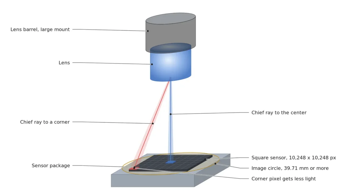
Point a flashlight straight at a wall and you get a round, crisp circle. Tilt your wrist so it hits the wall at a slant, and the circle stretches into an oval and fades. The amount of light is the same. It simply lands on a larger area. The bigger the sensor, the more its corner pixels receive this slanted flashlight beam, and on a 100 MP sensor that slant shows up as a number in the image brightness.
On November 11, Sony said the monochrome model of its 105-megapixel global shutter1 sensor, the IMX927, entered mass shipment in October. It is a square sensor with 10,248 rows and columns of 2.74 μm pixels, 28.08 mm on a side and 39.71 mm on the diagonal. It is published as reading 111.7 frames per second at 8 bits, so 100 MP sensors are now moving past the lab bench and onto inspection stations.
The target is a single PCB panel, 140 mm on each side. The green solder resist is a semi-gloss surface that scatters light back evenly, while solder fillets and bare copper pads throw light in one direction by specular reflection2. On an image with such mixed reflectance, if only the corners darken, a fixed threshold reads healthy resist in the corners as defects, and lowering the threshold lets shallow scratches in the center slip through. So when I get a sensor like this, I calculate the four corners before the center pixels.
A 39.71 mm diagonal is wider than the C-mount thread
The C-mount, the most common mount on machine vision cameras, holds the lens on a thread one inch, 25.4 mm, in diameter. The diagonal of this 100 MP sensor is 14.3 mm longer. The round image a lens forms, the image circle3, has to cover the sensor diagonal for the corners to receive an image, and when the thread itself is narrower than the sensor, a C-mount lens cannot even reach the starting line. The same arithmetic explains why the Allied Vision hr927 series built on this sensor uses an M58 mount as standard and offers a separate Canon RF mount model.
Seen from the film camera side, the shape is familiar. Put a hood made for a telephoto lens on a wide-angle lens, and the four corners of the picture are eaten away into dark rounded patches. The opening of the hood is narrower than what the lens wants to see, and an image circle smaller than the sensor leaves a shape much like those dark corners. This one can be screened out in advance from a single number on the spec sheet, which makes it the easier problem.
The harder one is the darkness that remains after the image circle comfortably covers the diagonal. Even when the lens forms the whole image, a corner pixel receives less light than a center pixel. By my standard, the image circle is only a pass condition when choosing a lens for a large sensor; whether it qualifies comes down to what percentage of light is left at the corners. That percentage is set by the angle at which light arrives.
Light reaches a corner pixel at a slant and lands thin
The ray that passes through the center of the lens aperture and reaches a point on the sensor is called the chief ray, and the angle it makes with the sensor normal is the chief ray angle4. At the center of the image the chief ray falls almost straight down, but toward the corners it leans over. The closer the lens sits to the sensor, and the larger the sensor, the larger this angle grows. The corner 19.86 mm out, half of the 39.71 mm diagonal, is the spot the calculation below follows.
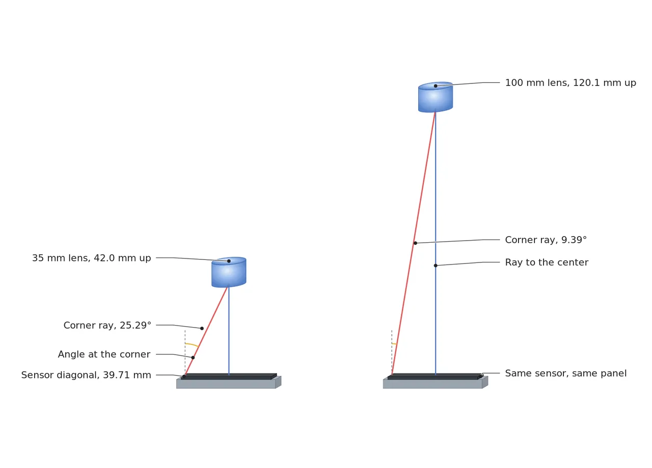
In the figure, the ray to the corner pixel travels a longer, slanted path than the ray to the center pixel. Seen at a slant, the lens opening shrinks into a flat oval; the longer distance thins the light with its square; and the tilted light spreads over a wider area like the flashlight. Together these three make corner brightness fall as cos θ of the chief ray angle θ multiplied four times. Edmund Optics describes this drop, which occurs even with no vignetting clipping the light in the lens, as cosine-fourth roll-off5, and its table shows brightness going from 98.5 % at 5° down to 6.3 % at 60°. If the corner angle is 25.29°, cos θ is 0.904, and multiplied four times it becomes 0.668. A number close to 1 shrinks fast once you multiply it four times.
Two more effects stack on top. One is vignetting, where the edge of the lens barrel cuts off part of the slanted light; the other is sensor-side roll-off, where the tiny collecting lens on each pixel accepts slanted light less well. Both differ from lens to lens and sensor to sensor, so public data alone cannot calculate them. The numbers below include cos⁴ only, and I recommend reading them on the assumption that real corners are darker.
With a 35 mm lens the four corners are 33 % darker
Fitting a 140 mm panel onto the 28.08 mm sensor side gives a magnification6 of 0.2006x, and one pixel on the panel is 13.66 μm. By my standard of seeing a scratch across at least three pixels, 41.0 μm becomes the smallest width this setup can catch. The calculation uses a thin-lens approximation and assumes the image of the aperture through which light exits sits at the lens position. The distance from lens to sensor is then 1.2 times the focal length, and the corner chief ray angle is the arctangent of 19.86 mm divided by that distance.
With a 35 mm lens, the sensor is 42.0 mm away, the corner angle is 25.29°, and cos⁴ is 0.668. At an exposure that puts the center at 200 in 8 bits, the corner sinks to 134, a brightness loss of 33.2 %. At 50 mm this falls to 18.3° and 18.8 %, at 100 mm to 9.39° and 5.3 %, and at 150 mm to 6.29° and 2.4 %. The longer the focal length, the farther the lens sits from the sensor and the less steeply it sees the corners. The difference comes from where the lens sits.
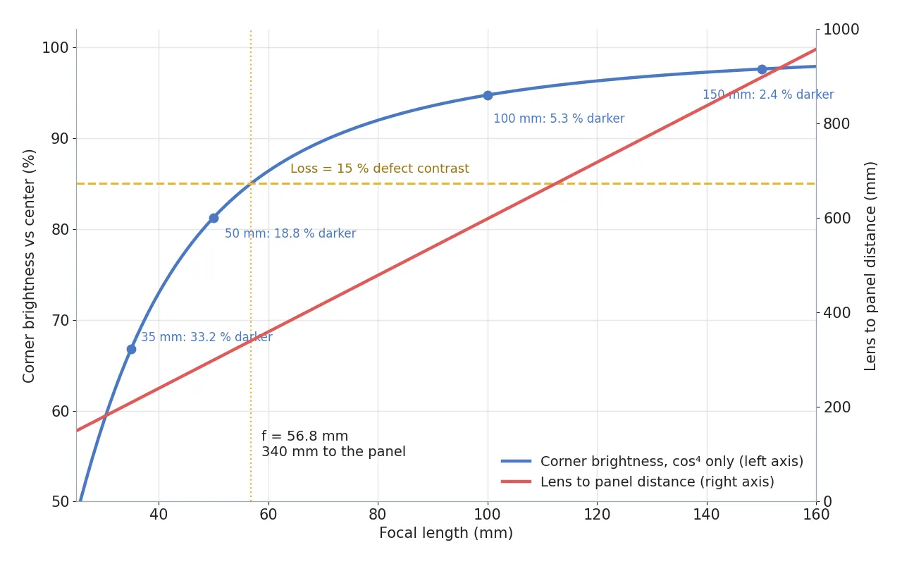
The blue curve in the graph is the brightness left at the corners, and the red curve is how far the lens has to sit from the panel to keep the same magnification. If a scratch shows up 15 % darker than the background, then the moment corner roll-off exceeds that 15 %, a healthy corner becomes darker than the scratch. The yellow dashed line marks that boundary; the focal length where the blue curve crosses it is 56.8 mm, and the distance to the panel there is 340 mm.
33.2%
Brightness a corner loses with a 35 mm lens (cos⁴ only, calculated)
56.8mm
Shortest focal length that keeps corner roll-off below a 15 % defect contrast
340mm
Lens principal plane to panel, at that focal length
Of these three numbers, the one I weigh most is the last, 340 mm. The price of saving the corners does not appear on the lens price tag; it is billed as station height. Save the height, and that share passes to software.
Software can even out brightness, but the noise stays
The standard way to flatten dark corners is shading correction7. You first photograph an even white plate to get a brightness gain for each pixel, then multiply the inspection image by that gain. The reference plate has to be shot again whenever the lens, aperture, or lighting changes. Core Logic’s US7834925B2 describes dividing the image into blocks and giving each block a brightness weight, and Imagination Technologies’ US8970744B2 describes deriving a two-dimensional correction function per lens and storing only a few sample points. The 134 at the corner of the 35 mm lens climbs back to around 200 when multiplied by a gain of 1.5.
Trusting correction alone
Dark corners are something one pass of shading correction fixes.
Run the numbers
Correction matches brightness only. At a corner where fewer light particles piled up, the noise stays 1.22 times larger.
Multiplication does not tell signal from noise. Counting only the noise from the random arrival of light particles, the signal-to-noise ratio8 follows the square root of the light collected, and the corner of the 35 mm lens stays at 0.817 times the center. Even after correction lifts the brightness to 200, the fluctuation there is 1.22 times larger than at the center. Set one threshold across the whole image to separate a scratch from noise, and only the corners see noise cross it, so false calls pile up there.
Lengthening the exposure to fill the corners is blocked too. Raise an exposure that gave 200 at the center by 1.5 times, and the solder glints in the center hit 255 and turn white. That area is erased. Because software image processing alone cannot fully cover a light shortfall created by the lens and sensor, I reduce corner roll-off as far as the optics allow before handing it to correction.
The station grows taller with every step up in focal length
The handle the optics side can turn is focal length. Put a 100 mm lens in front of the 100 MP sensor, and corner roll-off drops to 5.3 %, but the panel has to sit 599 mm from the lens principal plane. The real WD9 is measured from the front of the lens, so it is shorter than that, and you have to confirm the value separately on the lens spec sheet. In exchange, a wide space opens between lens and panel, which makes it easy to bring in large diffuse lights at an angle to cover the 140 mm panel evenly.
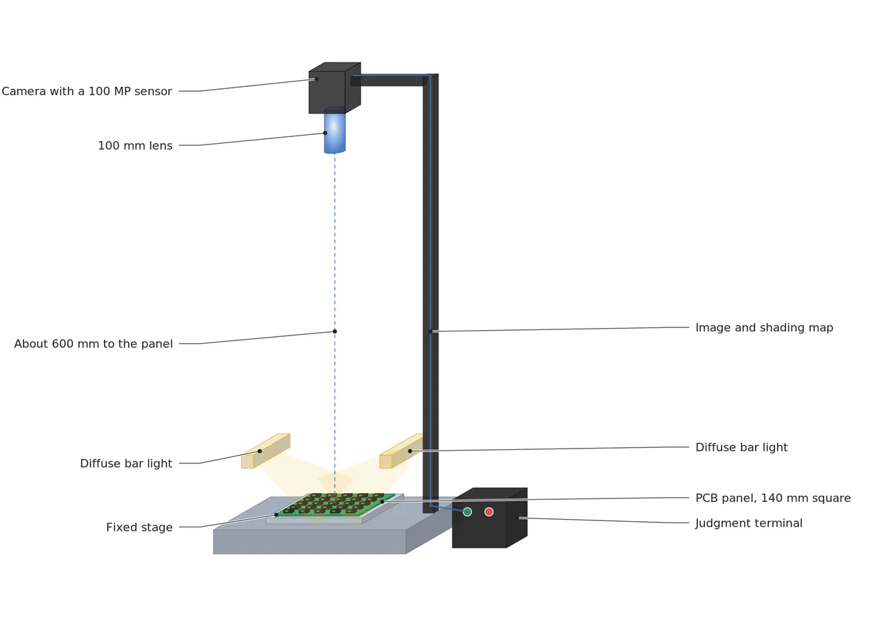
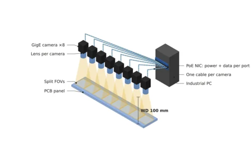
In the station in the figure, the camera stands about 60 cm above the panel, and two rows of diffuse light shine on the panel from both sides. The evenness of the lighting itself also lands on the corners: as the panel edges move away from the center of the lights, the lighting falloff stacks once more on top of the lens cos⁴. I would put down a white reference plate and measure the corner-to-center ratio while changing only the lighting. Carried over to the first page of a spec sheet, this setup reads as follows.
| Item | Value | Condition and basis | In plain words |
|---|---|---|---|
| ① Minimum defect size | 41.0 μm (3 px) | Magnification 0.2006, 13.66 μm per pixel on the panel, one 140 mm panel | Even a 41 μm scratch spans three pixels |
| ② Optical setup | 100 mm focal length, image circle 39.71 mm or more, M58-class mount, f/5.6, diffuse lights on both sides | Corner roll-off 5.3 % (cos⁴), 599 mm to the panel, real WD to be confirmed from the lens front | Raise the lens so it sees the corners less steeply |
| ③ Algorithm parameters | Shading gain up to 1.06, corner threshold allows 1.03 times the noise | cos⁴ 0.947, signal-to-noise ratio 0.973 times (photon noise only) | A small correction lets one threshold cover the whole image |
The three rows show that once the corners are saved optically, the algorithm’s job shrinks to a correction gain of about 1.06. At f/5.6 the working f-number on the panel side becomes 6.72, so the Airy disk10 is 9.02 μm across, the size of 3.29 pixels, and the depth of field11 with an allowed blur of two pixels is 1.83 mm. If the component heights on a panel exceed this range, stopping down further means accepting more blur. How strongly solder glints change angle and turn white at the corners differs from panel to panel, so these values also cannot be guaranteed before a sample test.
There are clear cases where a short lens wins. If the height inside the machine cover cannot exceed 40 cm, or the defects you look for are more than 33 % darker than the background and do not drown in corner roll-off, a 35 to 50 mm lens with shading correction makes a smaller, cheaper station. Which side fits only shows once the defect contrast of the real panel and the machine height are measured, and I will not settle on either side before shooting samples.
Finishing this calculation at the spec sheet stage falls to the machine vision engineer who sits where the camera gets chosen, and for a newcomer, getting the cos⁴ and magnification formulas into your hands is enough to make a large-sensor spec sheet read differently. When weighing equipment cost, one 100 MP sensor can stand in for four 26 MP-class cameras and cut camera count and wiring, while a large-mount lens and a taller station structure take back part of that difference. One lens, two lights, and one camera shooting the whole panel at once also simplify alignment and calibration, but that advantage survives intact only in a setup that saves the corners optically. This article explains technology and is not investment advice. See our Disclaimer.
Field Note
If I build a panel station with this 100 MP sensor, I place a plain white diffusing plate on it before any PCB. I mount a 100 mm lens 599 mm above the panel height, take one picture with the lights off and the center brought to 200 by exposure alone, then one with the lights on, and write down the corner-to-center ratio for each. If the first ratio is far below the cos⁴ value of 0.947, I suspect vignetting in the lens barrel or sensor-side roll-off, and I stop down one step and shoot again. Vignetting shrinks as you stop down, while cos⁴ stays where it is.
Field Checkpoints
Once the two white-plate pictures from the field note split corner roll-off into the lens share and the lighting share, what remains is setting the station dimensions and the range of correction. Before you fix the setup, I recommend checking the following.
- Is the WD from the lens front to the panel really available, and is there height left for two rows of diffuse light in between? (599 mm measured at the lens principal plane, minus the lens length)
- Is the lens image circle 39.71 mm or more, and does the mount match the M58 or RF on the sensor side? (A C-mount lens cannot form an image out to the corners)
- How far does the corner-to-center brightness ratio on the white reference plate differ from the cos⁴ value? (A large gap means vignetting or sensor roll-off has stacked on)
- Where the shading gain is largest, does the noise stay below the threshold? (Check the fluctuation in corners that correction has brightened)
- Does the component height range on the panel fit within the 1.83 mm depth of field? (Whether the tops of tall parts and the board surface are sharp together)
- Do solder glints at the corners turn white at a different angle from the center? (Confirm with real panels as samples)
Frequently asked questions
Does reading at 5,120 × 5,120 reduce corner roll-off?
It does not. The IMX927 is published as delivering 200 frames per second at 10 bits in its 5,120 × 5,120 subsampling mode, but subsampling leaves the sensor size and the distance to the corners unchanged, so the chief ray angle is the same. Fewer pixels make each pixel on the panel larger, and only the minimum defect size grows.
Can I use the same numbers for the color model?
If the pixel size and sensor size are the same, the cos⁴ calculation is the same. The published 2.74 μm pixel and frame rates, however, come from the color model flyer, and the model confirmed in mass shipment is the monochrome one. Pixels with a color filter on top may accept slanted light over a different range than monochrome pixels, so sensor-side roll-off should be measured separately.
Glossary
- [1] Global shutter global shutter
A readout in which every pixel starts and stops its exposure at the same instant. A moving part does not lean in the image, because no row is taken at a different moment. ↩ - [2] Specular reflection specular reflection
Reflection from a smooth surface that sends light out in one direction, at the same angle it came in. It is why a solder surface turns white at one angle and black at another. ↩ - [3] Image circle image circle
The diameter of the round image a lens forms on the sensor side with usable brightness and sharpness. The sensor diagonal has to fit inside this circle for the corners to receive an image. ↩ - [4] Chief ray angle chief ray angle, CRA
The angle between the sensor normal and the ray that passes through the center of the aperture to a given point on the sensor. It is close to 0° at the center and grows toward the corners. ↩ - [5] Cosine-fourth roll-off cos⁴ roll-off
The drop in brightness at the sensor in proportion to the fourth power of cos θ, where θ is the chief ray angle. It happens even when the lens barrel clips no light. ↩ - [6] Magnification magnification
How many times larger the image on the sensor is than the object. At 0.2x, 1 mm on the object becomes 0.2 mm on the sensor. ↩ - [7] Shading correction shading correction, flat-field correction
A process that photographs an even reference plate, derives a brightness gain for each pixel, and multiplies inspection images by it. It lifts dark areas, and it raises the noise there by the same gain. ↩ - [8] Signal-to-noise ratio signal-to-noise ratio, SNR
How many times larger the signal a pixel receives is than the fluctuation of that signal. Counting only the noise from the random arrival of light particles, it scales with the square root of the signal. ↩ - [9] WD working distance
The distance from the front of the lens to the surface under inspection. Lighting has to fit into that gap, so this distance sets most of the height of the setup. ↩ - [10] Airy disk Airy disk
The size of the smallest spot of light formed as light spreads through a round aperture. Its diameter is roughly 2.44 × wavelength × working f-number, and it grows as you stop down. ↩ - [11] Depth of field depth of field, DOF
The depth above and below the focus plane that stays sharp at the same time. It widens as you stop down and narrows as magnification rises. ↩
References
- Y.M.Cinema Magazine, Sony Begins Mass Shipping Its Flagship 105MP Global Shutter Sensor: 10K at 100 FPS (November 11, 2026; monochrome model in mass shipment from October, 2.74 μm pixel, 39.7 mm diagonal, 111.7 fps at 8 bits, 200 fps at 10 bits in 5,120 × 5,120 mode; pixel and speed values from the color model flyer)
- 1stVision, Allied Vision hr927M100GE (10,248 × 10,248 px, 2.74 μm, M58 standard mount, Canon RF and flat-front models)
- Edmund Optics, Sensor Relative Illumination, Roll-Off, and Vignetting (cos⁴ roll-off, 98.5 % at 5° and 6.3 % at 60°, sensor roll-off and vignetting)
- US patent US7834925B2, Core Logic Inc., Lens shading correction device and method in image sensor (filed 2007, lens shading correction with per-block brightness weights)
- US patent US8970744B2, Imagination Technologies Ltd, Two-dimensional lens shading correction (filed 2009, a per-lens two-dimensional correction function stored as sample points)
- Formulas: magnification m = sensor side ÷ panel side, image distance = f × (1 + m), object distance = f × (1 + 1/m), corner chief ray angle θ = atan(half diagonal ÷ image distance), brightness ratio = cos⁴θ, SNR ratio under photon noise = √cos⁴θ, working f-number = N × (1 + m), Airy disk diameter ≈ 2.44 × λ × working f-number, depth of field ≈ 2 × working f-number × c ÷ m²
Related reading — Why Are the Ends of a Line Scan Image Dark? · A Machine Vision Lens Calculator That Catches the FOV Error a Shortcut Formula Misses · In SWIR, One Stop Down Erases a 3.4 μm Pixel

Noctvision
An engineer who has handled mechanical design and project management for production equipment since 2005. Here I work through the cameras, lenses and lighting that go into equipment with formulas and public data, and record the assumptions and sources alongside the numbers.

You May Also Like
Catching 20 μm Sink Marks on High-Gloss Molded Parts with Phase Measuring Deflectometry
Vision Types Split First by Wavelength and Pixel Size