Why the PoE Network Card Sets the Limit on Your Optical Setup in a Multi-Camera Inspection Line
OPTICS
On a line where eight cameras each send 100 MB/s, gathering them on one PoE switch and running a single 1 GigE link to the PC means pushing 800 MB/s through a 125 MB/s pipe.
For an eight-camera setup that splits both sides of a PCB to catch 30 μm defects, I started from pixel resolution and calculated the PoE power budget, port bandwidth and trigger skew.
About 11 min read
The target is the top and bottom of a PCB 90 mm wide. Green solder mask scatters light, while copper pads and gold-plated connectors throw it back in one direction like a mirror, so brightness differs widely under the same lighting. On strongly reflective spots like gold plating, a slight change in lighting angle makes a highlight look like a defect or covers a scratch. With that surface condition noted first, I follow here the numbers that appear as the camera count grows.
When you grow an inspection line to four or eight cameras, cabling and power tend to be where the trouble starts. If some ports fail to power their cameras partway through the expansion and the cameras reboot, or bandwidth runs short and frames drop, the boards that should have been in those frames pass uninspected. The cost of tearing out the wiring comes after that.
PoE1 carries power and data on one cable and cuts wiring, but every port has a ceiling on the power it can deliver and the data it can carry. So I keep power and bandwidth columns in the same table where the lens and lighting specs are set.
A 30 μm defect sets the camera count
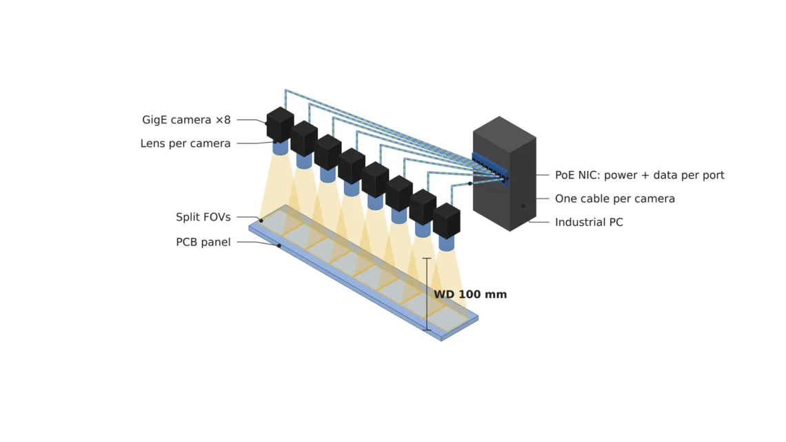
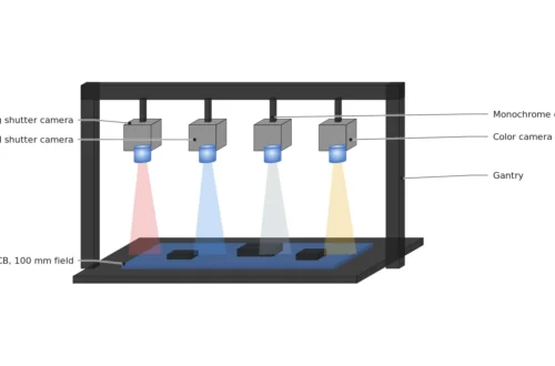
The camera count comes from the resolution requirement. Under my rule of putting a 30 μm defect into three pixels, the object-side pixel resolution2, the size of one pixel on the object, must be 10 μm or less, and covering 90 mm across in one frame would take 9,000 px. Assuming cameras 2,448 px wide with 3.45 μm pixels, each sees 24.5 mm at 10 μm per pixel, so four side by side with 2 mm of overlap at each seam cover 91.9 mm. Four on the top and four on the bottom make eight.
The lens is matched to a magnification3 of 0.345, an 8.45 mm wide sensor seeing 24.5 mm. With a 35 mm lens the distance from the lens center to the board is about 136 mm, which becomes the reference for the working distance WD4. To stand four in a row, the camera pitch must be 24.5 mm minus the 2 mm overlap, 22.5 mm, and if the camera body is wider than that, they cannot all fit in one row and must be staggered in a zigzag. Body width is a number too.
Power from one port shrinks in the cable
An IEEE 802.3af port sends out up to 15.4 W from the power sourcing equipment5, but the power guaranteed at the camera is 12.95 W. The 2.45 W difference is the share lost as heat in the cable, and it matches exactly the loss when the maximum current of 0.35 A passes the maximum standard resistance of 20 Ω: 0.35² × 20 = 2.45 W. 802.3at supplies 30 W and delivers 25.5 W, and the cable takes 4.5 W at 0.6 A and 12.5 Ω. The cable uses power too.
Assuming 5 W per camera, one 802.3af port is enough. If the power consumption in the camera spec sheet exceeds 12.95 W, though, an 802.3af port falls short and an 802.3at port is needed. Separate from the port class, the total PoE output the whole card can deliver is listed on its own line in the spec sheet, so I also check that 8 × 5 W = 40 W plus a 20 % margin, 48 W, fits inside it. Ports can look generous one by one and still hit the card total.
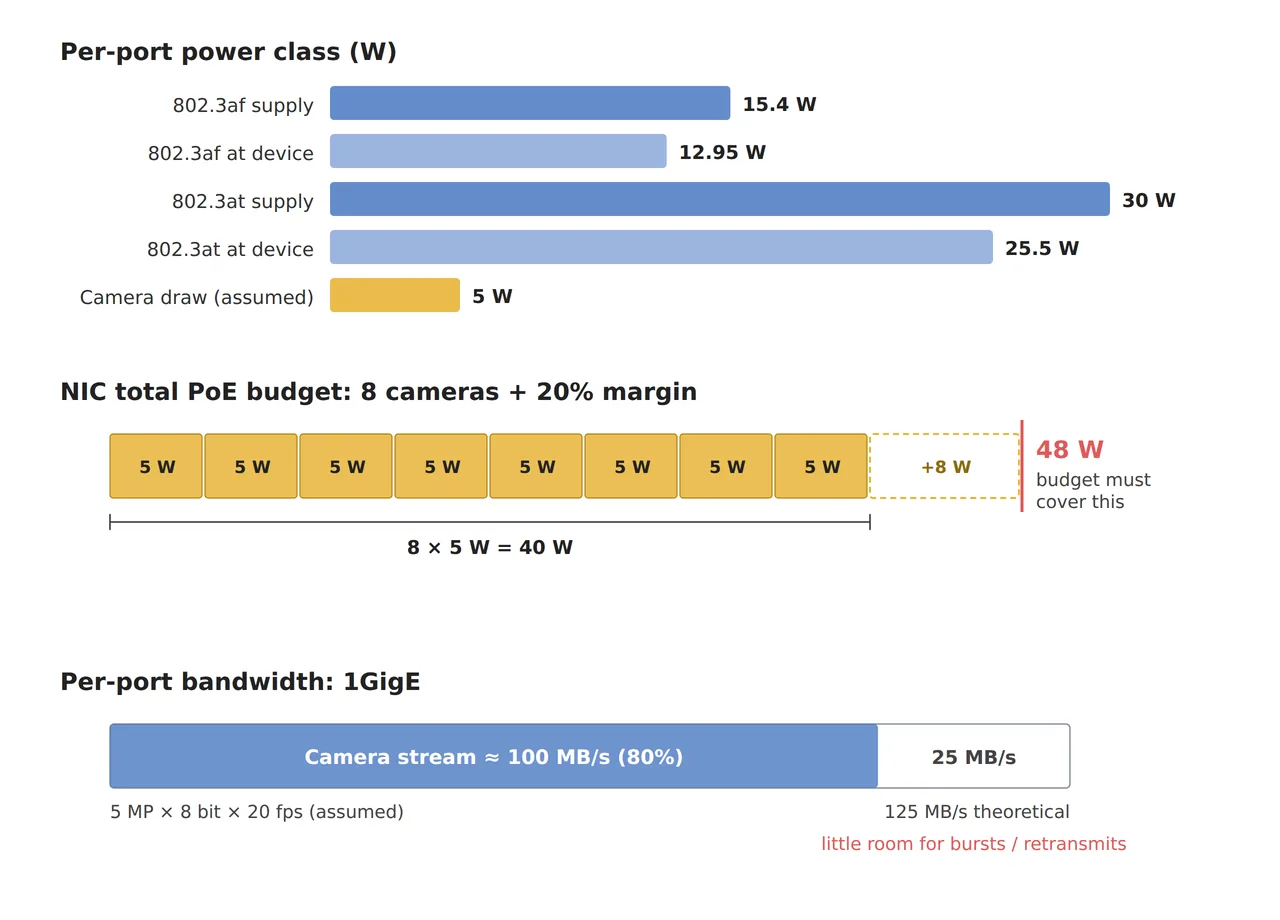
The figure is an allocation chart that puts the supply and delivered power of each port class, the 48 W total for eight cameras, and the 80 % of 1 GigE that one camera uses on a single page. The three are separate ceilings, so keeping only one does not finish the expansion.
Where the data from eight cameras meets one pipe
One frame from a 2,448 × 2,048 px, 8-bit monochrome camera is about 5.01 MB, and at 20 frames per second (assumed) that is 100.3 MB/s. It uses 80 % of the theoretical 125 MB/s bandwidth6 of 1 GigE, so with one camera per port it fits on average. In practice packet headers and resends7 eat into the remaining 20 %, and when data bunches up there is almost no margin. To cut the data per frame on the camera side, you can send only the region of interest used for judgment or lower the frame rate, and both values have to be set together with the inspection design. Either way, the size of what each camera sends is a design choice that belongs in the same table as the lens.
The problem is the junction where this data enters the PC. Connect all eight to one PoE switch and run a single 1 GigE link to the PC, and 802 MB/s has to pass through a 125 MB/s pipe, which cannot work. You need a multi-port card that gives each camera its own port on the PC side, or a 10 GigE link from the switch to the PC. With the theoretical 1,250 MB/s of 10 GigE, eight cameras use 64 %. The junction is the bottleneck.
Common belief
Tying eight cameras to one PoE switch simplifies the wiring, and that is the end of it.
Add up the total
With a single 1 GigE link from the switch to the PC, 802 MB/s must pass through a 125 MB/s pipe, and that one link is where frames drop.
The lens and pixels stay the same, yet one link of wiring splits the inspection result. If the expansion plan draws where the data converges alongside the camera count, this bottleneck shows up before any cable is pulled. Even one extra column for the MB/s total next to the camera count column makes it visible in the table.
When triggers skew, the seams shift
For eight cameras to split one board, they have to shoot at the same moment. If the board is shot standing still, trigger8 delay between cameras is not a big problem, but assuming it is shot while moving at 100 mm per second, a 1 ms skew becomes 0.1 mm, which is 10 pixels at 10 μm per pixel. That falls inside the 2 mm (200 pixel) overlap, so the seam does not open, but a defect in the overlap can land at different positions in the two cameras and be counted twice. For an inspection that judges by defect count, a rule assigning the overlap to only one camera has to be set in advance.
2.45W
Power lost as heat when 0.35 A passes a 20 Ω cable on an 802.3af port
80%
Share of the 1 GigE theoretical ceiling used by one 2,448 × 2,048 px, 8-bit camera at 20 frames per second
10px
Seam error from a 1 ms trigger skew when shooting while moving at 100 mm per second
If all eight cameras share a strobe light9, every camera's exposure has to fall within the short time the light is on. If the trigger skew is longer than the exposure window, some cameras shoot after the light goes off and only that section of the image comes out dark. That is why it is safer to tie the triggers with a hardware signal line instead of software commands.
Writing power and bandwidth into one table
Put power, bandwidth and trigger columns beside the lens and lighting columns, and you can see which column overflows when one more camera is added. Comparing the same optical setup with three kinds of wiring gives the table below. The optics column stays the same in all three rows, and only the wiring changes to show where the results split.
| Configuration | ① Minimum defect size | ② Optical setup · WD | ③ Algorithm parameters · in plain words |
|---|---|---|---|
| One per port, eight cameras | 30 μm = 3 px (10 μm/px) | 2,448 px with 3.45 μm pixels, 35 mm lens, WD about 136 mm (from the lens center), 24.5 mm view per camera, 2 mm overlap, eight 802.3af ports, 48 W total | 100.3 MB/s per port (80 %), keep the frame drop10 counter at 0, count defects inside the 200 px overlap only once |
| One switch, 1 GigE to the PC | 30 μm = 3 px | Same optics, a single 1 GigE link from the switch to the PC | A total of 802 MB/s has to pass a 125 MB/s pipe, so it cannot work |
| One switch, 10 GigE to the PC | 30 μm = 3 px | Same optics, 10 GigE from the switch to the PC (1,250 MB/s) | 64 % of the total used. Log resend requests to check the momentary margin |
Across the three rows, the table shows that the optics column is identical and the results split at the junction where the data converges. On the other hand, for a line where few cameras and low frame rates keep the total within 80 % of 125 MB/s, such as four cameras at 5 frames per second for 100 MB/s in total, one switch with a single 1 GigE link is enough and a multi-port card is more than the job needs. Whether this setup actually creates defect contrast on strongly reflective spots like gold-plated connectors cannot be guaranteed before a sample test.
An expansion plan starts from one table
When reviewing a camera expansion, I add cameras one row at a time and recalculate the power total and bandwidth total in the same table. With four-port cards, the moments the camera count passes the port count, at the fifth and ninth cameras, and the moment it passes the total PoE output show up in the table ahead of time. If you are just starting, I recommend working through 0.35² × 20 = 2.45 W once by hand. Why the spec table lists 15.4 W and 12.95 W comes down to that one line.
Filling in the power and bandwidth columns early in the design cuts down on tearing out wiring partway through an expansion. For whoever holds the budget, a multi-port PoE card and 10 GigE gear are easy items to overlook, but one dropped frame is one board that passed uninspected, which makes them a cost not to treat lightly. This article explains technology and is not investment advice. See our Disclaimer.
Field Note
If I bring up this configuration, I read the per-port power with the card management tool or a power meter while all cameras are running, and check that a 20 % margin remains against 48 W. Next I run all eight at 20 frames per second for an hour and log the frame drop counter and resend requests. If even one frame drops, I look again at that port's cable length and grade.
Field Checkpoints
Once the one-hour test shows zero drops, finish the spec with the questions below.
- Is a WD of about 136 mm (35 mm lens, from the lens center) secured with room for the lighting and cable bends? (whether the connector and cable behind the camera clear the structure)
- Does the camera body width fit within the 22.5 mm camera pitch? (if not, whether you used a zigzag layout)
- Does the power per camera fit within the delivered power of the port class? (12.95 W for 802.3af, 25.5 W for 802.3at)
- Does 48 W, the eight-camera total plus a 20 % margin, fit within the card's total PoE output? (whether you checked the total output line in the spec sheet)
- Can the bandwidth at the junction where data converges carry the total? (802 MB/s for eight cameras cannot go over a single 1 GigE link)
- Did you confirm with samples that defect contrast appears on gold-plated connectors and copper pads? (whether you avoid concluding from calculation alone on strongly reflective spots)
Frequently Asked Questions
Does a separate power cable instead of PoE remove the problem?
A separate supply removes the port power limit, but each camera gains a power cable and the bandwidth problem stays. If the camera power exceeds the 802.3at delivered limit of 25.5 W or the cable route goes beyond the standard, a separate supply is right; otherwise the PoE advantage of fewer cables is large.
Will a long cable leave the camera short of power?
The delivered power of 12.95 W in the standard already subtracts the loss of the longest cable the standard allows, so with compliant wiring the power reaching the camera is guaranteed. Thinner cable than the standard or many intermediate connectors raise the resistance and the loss, though, so it is safer to read the actual power per port once after installation.
Glossary
- [1] PoE Power over Ethernet
A method that sends data and power together over one network cable. Each class, such as 802.3af or 802.3at, sets the port power. ↩ - [2] Object-side pixel resolution object-side pixel resolution
The length one pixel covers on the object. It is the view divided by the horizontal pixel count, written in μm/px. ↩ - [3] Magnification magnification
The size of the image on the sensor divided by the size of the object. Seeing 24.5 mm with an 8.45 mm wide sensor gives 0.345. ↩ - [4] WD working distance
The distance from the lens to the surface being inspected. The text uses a thin-lens value measured from the lens center. ↩ - [5] PSE and PD power sourcing equipment, powered device
The PoE standard's names for the side that sends power (PSE, a card or switch port) and the side that receives it (PD, the camera). ↩ - [6] Bandwidth bandwidth
The amount of data one link can send per second. 1 GigE has a theoretical ceiling of 1,000 Mbit/s, or 125 MB/s in bytes. ↩ - [7] Resend packet resend
A request to send again a piece of data lost on the way. More resends use more bandwidth. ↩ - [8] Trigger trigger
The signal telling a camera to shoot now. When several cameras are tied together, the signal goes to all of them on the same line. ↩ - [9] Strobe lighting strobe lighting
Lighting that fires short and strong only at the moment of exposure. When several cameras share it, their exposure timing must match. ↩ - [10] Frame drop frame drop
A frame shot by the camera that never reaches the PC. The board that should have been in it passes uninspected. ↩
References
- Wikipedia, Power over Ethernet (standard comparison table: 802.3af 15.40 W supplied, 12.95 W delivered, 350 mA, 20 Ω maximum cable resistance; 802.3at 30.0 W supplied, 25.50 W delivered, 600 mA, 12.5 Ω), accessed October 24, 2026
- Formulas: pixel size = view ÷ horizontal pixel count; camera count = (width to cover − overlap) ÷ (view per camera − overlap), rounded up; cable loss = current² × resistance; data rate = width × height × bytes per pixel × frames per second; 1 GigE theoretical ceiling = 1,000 Mbit/s ÷ 8 = 125 MB/s; seam error = travel speed × trigger skew
- Assumed values: a 2,448 × 2,048 px camera with 3.45 μm pixels, 5 W power draw and 20 frames per second, a 90 mm board width, 2 mm overlap and 100 mm/s travel speed are assumptions for the worked example
Related reading — When You Add Cameras to a Semiconductor or PCB Line, the Interface Rewrites the Optics · Camera Interface Bandwidth Determines Resolution · Keeping Frame Rate and Lighting from Colliding on a High-Speed Inspection Line

Noctvision
An engineer who has handled mechanical design and project management for production equipment since 2005. Here I work through the cameras, lenses and lighting that go into equipment with formulas and public data, and record the assumptions and sources alongside the numbers.


You May Also Like
Raising the Camera Leaves the Glint of Its Built-in Light in Place
A Board at 0.5 m/s Leans 15 mm Under a Rolling Shutter