In the Age of Deep-Learning Inspection, What to Check Before Camera Spec
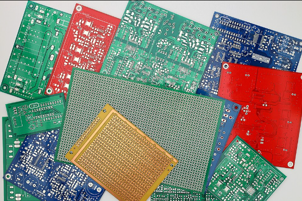
I recently came across news that a supplier of industrial cameras and frame grabbers had signed a string of distribution agreements with companies specializing in AI deep-learning inspection and industrial vision sensors. This isn’t a coincidence — it’s part of a trend where hardware suppliers are expanding their software portfolio. On an SMT (surface-mount technology) line, 30–50 µm-class micro-cracks, foreign matter, and bridge defects slip cleverly past a rule-based algorithm’s threshold and leak through, which then comes back as field claims and a drop in trust. In the end, the answer is to lock down the hardware optical setup first, and layer deep-learning classification on top of it.
The structural limits of rule-based algorithms
Rule-based inspection has its decision criteria themselves shift with even a slight wobble in lighting angle or exposure condition. Because the threshold depends on a fixed contrast difference, the same defect reads differently once illuminance (lx) changes. On a highly reflective metal surface like a solder bridge, for example, the diffuse-reflection pattern shifts with capture angle, so a defect that was caught yesterday genuinely can pass through today. So lowering the threshold to reduce missed detections raises false detections, and going the other way raises leakage — a trade-off that isn’t easy to escape.
The gap deep learning fills, but optics still has to come first
Deep-learning classification statistically eases this trade-off. Including a variety of lighting variations in the training data makes it possible to judge whether something is a defect based on the whole feature pattern rather than a single threshold. But this only holds when the training data’s quality is already good. If camera resolution is insufficient, or the lighting placement is off so that a crack was never captured in the image to begin with, no matter how sophisticated the model, it cannot manufacture information that doesn’t exist. It’s the same as how, with an out-of-focus vintage lens, no amount of swapping film ever brings the image into sharp focus. The order has to be respected: optimize the optical setup first, and let deep learning add its refinement in judgment on top of that result. In particular, a surface like an SMT component, where a metallic-gloss area and a matte resin area are mixed together, has significant reflectivity variation, so the effect of a specific lighting method cannot be confirmed before actual sample testing.
Below is the minimum framework that hardware and algorithm need to align on together, assuming PCB SMT inspection.
| Category | Item | Baseline |
|---|---|---|
| Detection target | Minimum defect size | Roughly 30–50 µm (micro-crack/foreign-matter/bridge baseline) |
| Optical setup | Lighting and lens | Coaxial epi-illumination + telecentric lens (25–50 mm focal length), WD 50–100 mm secured |
| Algorithm parameters | Deep-learning detection criteria | IoU threshold 0.5 or higher, training dataset at least several thousand images, inference confidence threshold 0.7–0.8 |
What this table shows is clear. Once defect size is set, the matching resolution and WD are decided first, and the deep-learning parameters are only a downstream variable fine-tuned on top of that.
Field Checkpoints
- Has the target surface’s material and reflectivity been checked first (a material with heavy diffuse-reflection variation cannot be confirmed before sample testing)?
- Are camera resolution and lens magnification sufficient for the target defect size (µm)?
- Is WD (working distance) in the lens-lighting layout achievable without conflicting with the actual installation space?
- Does the deep-learning training data sufficiently cover lighting variation and defect types?


You May Also Like
It Worked Fine on the Server — Why Does Accuracy Drop on the Edge?

What Should a Camera See When a Humanoid Grasps an Object?