What You Must Check Before Applying INT8 Quantization to Edge AI Inference: Why Micro-Defects Quietly Disappear
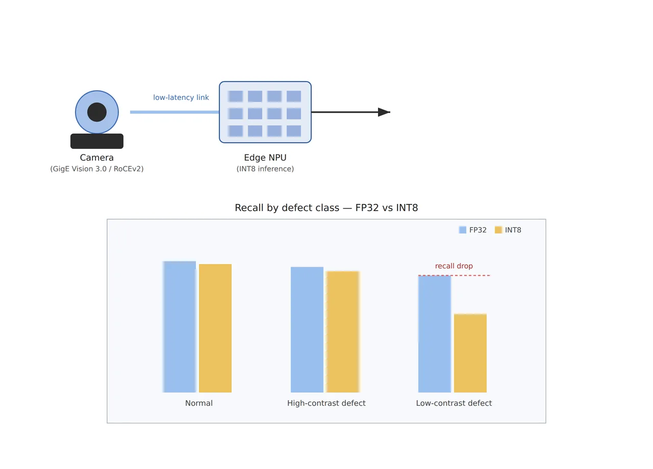
Moving a micro-scratch detection model on a PCB connector inspection line from a cloud server to an edge smart camera usually goes smoothly. The mAP (mean average precision) over the full validation dataset differs by only 1–2 percentage points before and after quantization, and inference speed becomes several times faster, so it’s easy to conclude in the field that “there’s no problem.” Yet weeks later, missed-detection leakage of scratch defects keeps recurring in specific lots. Tracing the cause reveals the problem isn’t the model’s overall average performance, but that accuracy has quietly dropped in just one defect class — one that already had inherently low contrast.
Leaving this unaddressed hardens the inspection line into a structure that “works well on average but selectively misses one specific defect type.” If you look only at aggregate metrics before deploying to mass production, the leakage rate of the low-contrast micro-defect class accumulates gradually and is often discovered only at a downstream process or the customer-claim stage. This article organizes why one specific defect class alone selectively loses accuracy when a model is quantized to INT8 for edge AI inference, and how the edge hardware and camera interface environment updated in the first half of 2026 interlocks with this problem.
Why quantization affects each defect differently
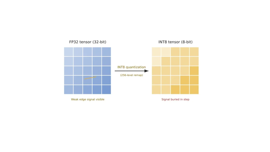
INT8 quantization used in edge AI inference is the process of compressing weight and feature-map values, originally represented in 32-bit floating point (FP32), into 8-bit integers. This compression works by dividing the value range by a scaling factor and remapping it into 256 integer steps, and the problem is that this remapping does not act identically across every layer and every feature of the neural network. A patent held by Korea’s Intellectual Discovery (US12335477B2) addresses this point precisely [see patent]. It explains that quantization of the feature maps produced by a multi-layer neural network should be performed differently per layer or per feature, based on the network structure or feature-map attributes. In other words, if every layer is quantized uniformly at the same bit width, the layers responsible for narrow dynamic-range, fine signals — such as the weak edge response produced by a low-contrast scratch — suffer relatively greater information loss.
This loss tends to go unnoticed because the class distribution of a validation dataset usually has far fewer defect samples than normal ones, and within those defects, low-contrast micro-defects are an even smaller minority. Overall mAP or accuracy is dominated by the performance of the majority classes (normal, high-contrast defects), so an accuracy drop occurring in a minority class gets buried in the average. Ultimately, a figure like “1–2 percentage points of accuracy difference before and after quantization” alone cannot tell you how far a specific defect class has shifted toward missed detection.
The edge AI inference hardware landscape is shifting
The hardware that actually runs edge AI inference is also undergoing a generational shift in 2026. The Raspberry Pi family’s AI HAT+ 2 replaced its accelerator from the earlier roughly-26-TOPS Hailo-8 with the Hailo-10H, delivering 40 TOPS of INT8 compute and 8 GB of dedicated LPDDR4X memory, designed so vision processing does not consume the host board’s system memory [2]. In the NVIDIA Jetson family, TensorRT combines FP16/INT8 precision calibration, layer fusion, and kernel auto-tuning to accelerate inference, and applying quantization-aware training (QAT) has been reported to process even complex vision tasks within 100 ms on a standard Jetson node [3].
However, these hardware performance gains only guarantee “faster inference” — they do not automatically guarantee “more accurate low-contrast detection.” There are reports that TensorRT’s INT8 quantization typically carries an accuracy loss on the order of 0.5–2.0 percentage points [3], but this figure is an overall average, and per-class deviation must be checked separately. A patent originally filed by LeapMind and now held by Maxell (US12242950B2) covers a neural network circuit structure embeddable in an edge device, proposing a structure that separates the memory unit storing convolution-operation output from the quantization-operation circuit, repeatedly re-feeding quantized data back in [see patent]. Optimizations at this circuit level improve computational efficiency, but the fundamental structure — where information gets cut off and at how many bits — still determines defect-detection performance in the end.
The link between GigE Vision 3.0 and edge inference
GigE Vision 3.0, approved by the A3 (Association for Advancing Automation) technical committee on April 17, 2026 and officially released on May 12, introduced streaming based on RoCEv2 (RDMA over Converged Ethernet v2) [1]. This means that when transferring images from camera to computer, direct memory access (RDMA) is possible without operating-system intervention, supporting high-throughput image capture with low CPU usage and low latency [1]. This may seem unrelated to edge AI inference at first glance, but in practice the two are closely linked. When transfer latency between camera and edge device drops, the inference-speed margin gained from quantization can be reinvested into higher resolution or frame rate. Conversely, if the transfer segment is the bottleneck, no matter how sophisticated an edge AI inference model you deploy, the update rate of the raw images coming from the camera itself limits the inspection cycle.
An Omron patent (US11361424B2) covers another axis of this pipeline, the image-processing module structure [see patent]. In a fully connected structure with one input-layer unit, multiple intermediate layers, and one output-layer unit, each intermediate-layer unit operates as an image-processing module, updating connection coefficients through backpropagation-based training — and this structure, too, presupposes that each layer handles information of a different character. Ultimately, the final performance of edge AI inference can be seen as determined by three axes working together: the camera interface (data-supply speed), the neural network structure (per-layer information characteristics), and the quantization strategy (bit-width allocation).
Core framework matching table
The table below is an example setup for detecting micro-scratches on PCB connector pins using edge AI inference. Actual parameters vary by defect type, model architecture, and edge-hardware combination, so confirmation is required before finalizing any spec.
| Category | Item | Value / Spec |
|---|---|---|
| ① Minimum detectable defect size | Connector pin micro-scratch baseline | 20 µm (example baseline, requires re-verification per target) |
| ② Optical setup — camera/interface | Camera interface | Camera supporting GigE Vision 3.0 (RoCEv2) or an equivalent low-latency interface [1] |
| ② Optical setup — lens/WD | Working distance | WD 60 mm secured (including clearance for edge-device/cable layout, example) |
| ② Optical setup — lighting | Reflectivity response | Coaxial epi-illumination as the default given connector specular characteristics (requires re-verification per target material) |
| ③ Algorithm parameters | Quantization method | Consider per-layer/per-feature-map differentiated quantization [see patent]; avoid uniform INT8 across all layers |
| ③ Algorithm parameters | Validation metric | Individually confirm per-defect-class recall in addition to overall mAP — mandatory |
| ③ Algorithm parameters | Target inference latency | Target total latency (camera transfer + inference) within 100 ms relative to line speed (example) [3] |
Takeaway: what this matching table shows is that the success of an edge AI inference deployment is not decided by a single hardware spec. Low-latency camera-interface transfer, the optical setup’s response to reflectivity, and per-class validation of the quantization strategy all have to work together to prevent leakage of low-contrast micro-defects.
When cloud/server inference is favorable instead
In an environment where line speed is slow enough to allow latency margin, the number of defect classes is large enough that per-class validation burden is heavy, and the inspection target changes periodically enough that the model must be frequently retrained and redeployed, it can be more favorable to run inference at FP32 or FP16 precision on a server/cloud rather than deploying a quantized model to an edge device. In that case, there’s no need to worry about per-class accuracy deviation from quantization in the first place, and model updates can be handled from a single server rather than redeployed to every edge device. However, this only holds on the premise that network latency and bandwidth can keep up with line speed, and results can vary depending on the actual defect-class composition, line speed, and network infrastructure combination, so it cannot be confirmed before sample testing.
Field Checkpoints
- Is the WD and cable layout between camera and edge device physically secured within the GigE interface’s cable-length limit?
- Has accuracy before and after quantization been compared individually by per-defect-class recall, not just overall mAP?
- Is the number of validation samples for the low-contrast defect class large enough for a statistically meaningful judgment?
- Has the total latency — camera transfer latency plus edge inference latency combined — been confirmed to fit within line speed (inspection targets per second)?
- Has the per-defect-class performance change from applying per-layer/per-feature-map differentiated quantization or QAT been recorded separately?
References
[1] Association for Advancing Automation (A3), “A3 Officially Releases GigE Vision 3.0, Opening New Possibilities in Machine Vision” (released 2026-05-12, approved by the GigE Vision technical committee 2026-04-17, RoCEv2 integration)
[2] Raspberry Pi AI HAT+ 2 product information (Hailo-10H accelerator, INT8 40 TOPS, 8GB LPDDR4X, up to 3W operation)
[3] NVIDIA Jetson TensorRT technical documentation — FP16/INT8 precision calibration, layer fusion, QAT-based low-latency inference cases
[see patent] US12335477B2 (Intellectual Discovery Co., Ltd., “Neural network feature map quantization method and device”, issued 2025-06-17, priority date 2020-11-18)
[see patent] US12242950B2 (originally filed by LeapMind Inc., current assignee Maxell, Ltd., “Neural network circuit, edge device and neural network operation process”, issued 2025-03-04, priority date 2020-04-13)
[see patent] US11361424B2 (Omron Corp, “Neural network-type image processing device, appearance inspection apparatus and appearance inspection method”, issued 2022-06-14, priority date 2018-03-14)


You May Also Like
It Worked Fine on the Server — Why Does Accuracy Drop on the Edge?

What Changes in Vision Inspection When Logistics Automation Moves Into the Front End