Six Machine-Vision Lighting Methods and How to Choose
It’s common to pick the camera and lens first and add lighting afterward. In practice it’s the other way around. Deciding what needs to be visible, and how, is what determines the camera and the lens.
There are cases where a problem that lighting could fix in five minutes gets fought with algorithms for days instead — stacking filter after filter trying to find a defect in an image with no contrast to begin with. None of that work would have been needed if the defect had simply been captured visibly in the first place.
This piece organizes six industrial lighting methods and the criteria for choosing which one fits which situation.
The Starting Point of Lighting Design — Three Questions
There are three things to answer before choosing a lighting method.
1. What Are You Detecting?
Different purposes need different lighting.
- Dimensional measurement — the outline needs to be accurate. Surface information isn’t needed.
- Surface defects — fine surface relief needs to be revealed.
- Part presence — only present/absent needs to be distinguished.
- Character reading — stamped or printed marks need to separate from the background.
Use lighting that shows the surface clearly for a dimensional measurement task, and outline judgment actually gets worse instead. The purpose is what determines the lighting.
2. What Is the Target Surface Like?
The same lighting produces opposite results depending on the surface.
| Surface | Light behavior | Caution |
|---|---|---|
| Specular (machined metal, glass) | Reflects at the same angle as incidence | The light source itself gets reflected directly, causing saturation |
| Diffuse (paper, molded parts) | Scatters in many directions | Relatively easy to work with |
| Transparent (film, bottles) | Passes through or refracts | Consider transmitted (back) lighting |
| Relief (machining marks, wrinkles) | Produces light/dark depending on angle | Use this property to emphasize defects |
3. Where Will the Contrast Come From?
Inspection ultimately comes down to a fight for contrast. You need to decide whether it will come from a brightness difference, from a shadow, or from a color difference. That decision is what leads to the choice of lighting method and wavelength.
Six Lighting Methods
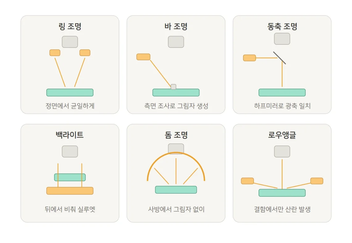
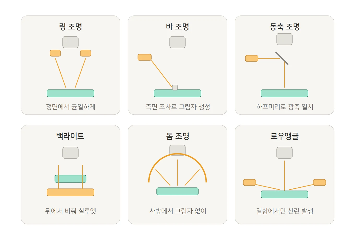
1. Ring Light
Principle — A circular light source surrounding the lens illuminates the target head-on. This is the most widely used method.
Good for — Checking the overall shape on a diffuse-reflection surface, judging part presence, confirming assembly state. The default choice when there’s no special requirement.
Not good for — A strongly specular flat metal surface. The ring shape itself gets reflected straight back, showing up as a donut-shaped bright band.
Caution — Brightness distribution changes significantly with the distance between the light and the target. Using a model with adjustable angle widens its range of usefulness.
2. Bar Light
Principle — A bar-shaped light source is placed to the side, illuminating at an angle. The lower the angle, the longer the shadows.
Good for — Emphasizing surface relief, scratch detection, reading stamped characters. Effective at converting surface height differences into light/dark contrast.
Not good for — An inspection that needs uniform brightness. The side near the light is bright while the opposite side goes dark.
Caution — Placing two bars facing each other on both sides improves uniformity, but that reduces the shadow effect by the same amount. Depending on the goal, using only one side can sometimes be the better choice.
3. Coaxial Light
Principle — A half-mirror sends light along the same direction as the lens’s optical axis. Light that strikes the target surface perpendicularly returns straight back.
Good for — Reading stamped characters on a flat metal surface, detecting scratches or foreign matter on a specular surface. Flat areas come out bright and tilted areas come out dark, so even a fine angle change shows up as light/dark contrast.
Not good for — A target that’s curved or has heavy surface relief. Most areas where light doesn’t return end up dark.
Caution — Light loss through the half-mirror is significant. A brighter light source is needed than with other methods.
4. Back Light
Principle — Light shines from behind the target, creating a silhouette. The target comes out black, the background white.
Good for — External dimensional measurement, checking hole position and size, shape judgment. This method produces the sharpest outline of any of the six.
Not good for — Surface-condition inspection. No surface information is captured at all.
Caution — Dimensional-measurement accuracy is directly governed by the lighting’s uniformity. If the edges are dim, the outline judgment in that area shifts inward.
5. Dome Light
Principle — Light bounces off the inside of a hemisphere, illuminating evenly from every direction. Almost no shadows form.
Good for — Checking printing or labels on a curved or glossy surface, cylindrical targets like cans or bottles.
Not good for — Detecting surface relief. No shadows means height differences don’t show up.
Caution — Structurally bulky. Can be hard to install in tight equipment space.
6. Low-Angle (Dark-Field) Light
Principle — Light is sent in at an angle nearly parallel to the target surface. On a flat area, light doesn’t return to the camera and it comes out dark; only where there’s a defect does scattering occur, showing up bright.
Good for — Fine scratch, foreign-matter, and crack detection. The most effective method for making only the defect stand out bright against a flat background.
Not good for — Confirming overall shape. The dark background makes it hard to make out the target’s outline.
Caution — Extremely sensitive to the distance and angle between the light and the target. Fixing it securely after installation matters.
Selection Criteria Summary
| Inspection purpose | Surface condition | Recommended lighting |
|---|---|---|
| Dimensional measurement | Irrelevant | Back light |
| Surface scratches | Flat/glossy | Low-angle, coaxial |
| Reading stamped characters | Metal | Coaxial, bar |
| Reading printed characters | Curved/glossy | Dome |
| Part presence | Diffuse surface | Ring |
| Relief/step height | Irrelevant | Bar |
| Foreign matter/cracks | Flat | Low-angle |
This table is a starting point. In practice, you often need to combine two methods, or search by varying angle and distance even within the same method.
Three Common Failures
The Misconception That Brighter Is Always Better
Turn the lighting up to maximum output and the image saturates. Bright areas all get crushed to the same value, and the information inside them disappears. If a defect happens to be in the bright region, it gets missed entirely.
It’s worth making a habit of checking the histogram to confirm the top isn’t pinned against the wall. The correct exposure isn’t the maximum brightness — it’s the brightness that retains the most information.
Leaving Stray Light Unaddressed
This is a common reason a setup that worked fine in the lab becomes unstable in the field. Overhead lighting, sunlight coming through a window, and indicator lamps from neighboring equipment can all have an effect.
A problem where results change with the season or the time of day is especially time-consuming to trace. It’s better to treat a light-shielding cover as a default, not an optional extra.
Setting the Lighting Angle Carelessly
Results from low-angle or bar lighting change completely with just a few degrees of difference. If you let it slide as “close enough,” it won’t reproduce later.
Record the angle and distance as numbers, and fix them in place with a mounting bracket so they can’t move. Lighting is an element that’s hard to change once it’s set.
Specific methods for handling strongly reflective surfaces are covered separately in How to Handle Imaging on Highly Reflective Surfaces.
Closing
An algorithm can be fixed later. Lighting structure can’t, not as easily. Once it’s built into the equipment, changing even a single angle can mean stopping the line.
That’s why lighting is worth the time investment up front. The recommended order is to review lighting before picking a camera.
Frequently Asked Questions
Q. What’s the first thing to decide when choosing machine-vision lighting?
Three things: what you’re detecting (dimension, surface defect, presence, character), whether the target surface is specular or diffuse, and where the contrast will come from. Lighting gets decided before the camera and lens.
Q. What lighting suits a strongly reflective surface, like a machined metal surface?
A specular surface favors a method that controls the direction of reflection, like coaxial or dome lighting; to bring out relief or scratches, use low-angle (dark-field) lighting.
Q. Does brighter lighting improve detection?
No. Saturation actually erases information. Recording angle and distance as numbers, and blocking stray light, matters more than brightness.
The content of this article summarizes general principles. Please validate against your own target and environment when applying it to an actual system design.
Related Reading — How to Handle Imaging on Highly Reflective Surfaces

You May Also Like
How to Handle Imaging on Highly Reflective Surfaces
2D/3D Fusion Inspection: The Bottleneck Is Lighting Interference