Is a Silhouette Dimension Accurate Just Because the Backlight Is On? — Reducing Edge Blur and Measurement Error on Thick Parts with a Collimated Backlight
LIGHTING / OPTICS
Silhouette dimensional measurement looks like the simplest inspection in machine vision. Place a backlight behind the part, trace the outline of the black shadow, and measure lengths and diameters — it seems that is all there is. Yet put a thick machined metal part or a connector housing on the stage, and the dimension wobbles by several µm every time the same part is placed again, and a constant offset remains between the caliper value and the vision value. Most sites blame this offset on the lens or the algorithm.
Left unaddressed, the cost shows up at the tolerance boundary. On a part with a tolerance of ±10 µm, if the measuring system consistently reads the edge a few µm inward, good parts near the boundary are scrapped as rejects, and some parts that actually exceed the tolerance pass. Even if an offset correction is entered to match, that offset changes with part thickness and side-wall finish, so it drifts again when the lot changes. The measurement result remains as a number, but nobody knows the confidence interval of that number.
A large share of this error comes not from the lens but from the angular distribution of the backlight. A diffuse backlight emits light in every direction, and part of it grazes and reflects off the side wall of the part, mixing into the edge of the silhouette. The solution is to first cut the angles on the illumination side with a parallel-light (collimated) backlight whose divergence angle is narrower than the acceptance angle of the telecentric lens, and then compute the sub-pixel edge on the edge profile that has been cleaned up in this way.
The precision of a silhouette measurement is decided at the point where the acceptance angle of the lens and the divergence angle of the illumination interlock.
1. Why the Edge of a Thick Part Blurs Under a Diffuse Backlight
Point. When a part with thickness is placed in front of a diffuse backlight, the silhouette edge is imaged not as a single point at the top corner of the part but as a transition zone created by the entire side wall.
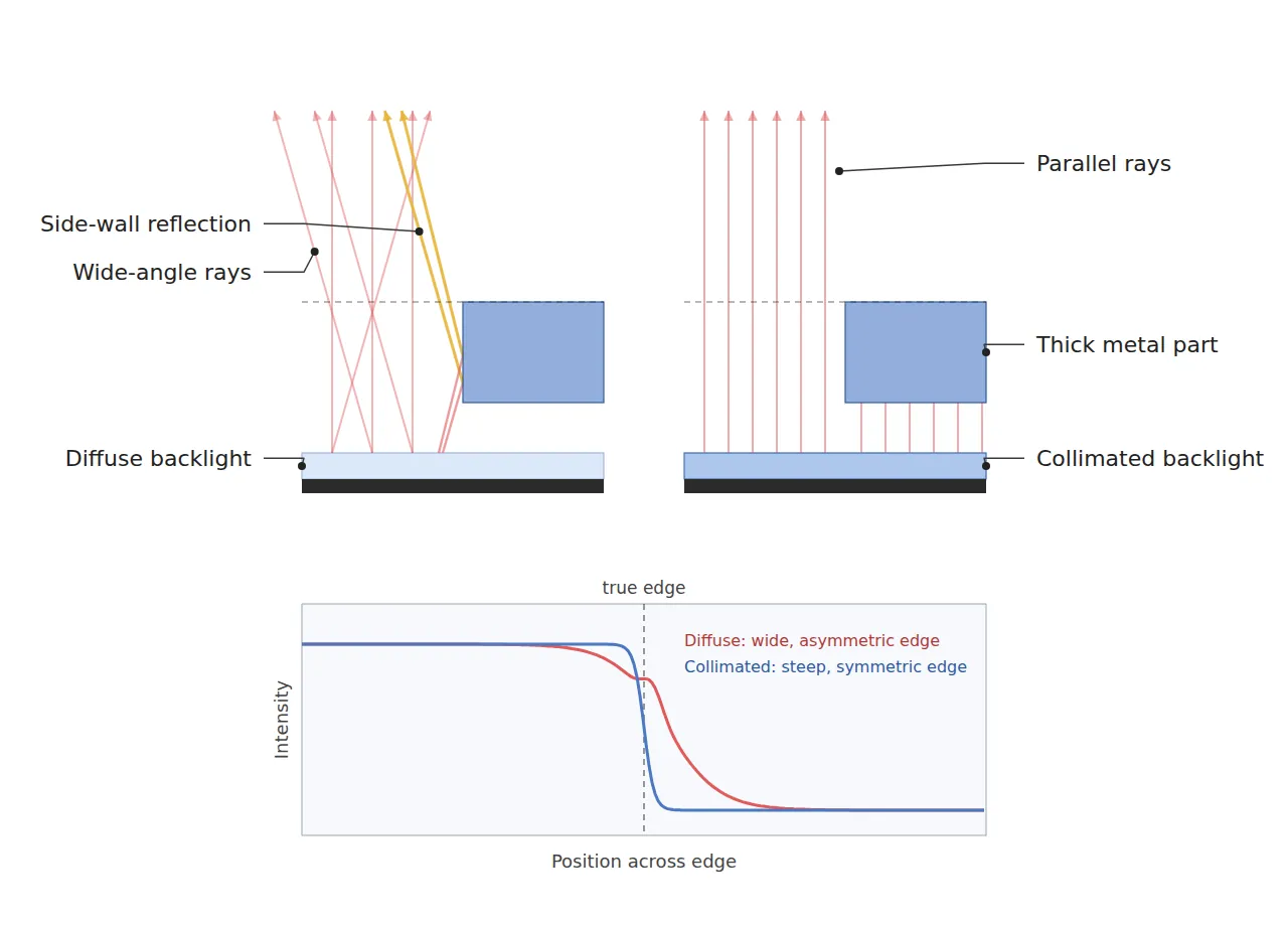
Reason. A diffuser emits light at nearly every angle, so within the angular range the lens accepts, rays graze the side wall of the part while tilted. With focus set on the top surface, a tilted ray is reflected or blocked deep along the side wall and then enters the pixels just outside the edge. Geometrically, the width of this transition zone does not exceed roughly part thickness t × tan(ray tilt θ). If the side wall is glossy, the reflected light adds and the edge smears bright; if it is matte, the light is absorbed and the edge smears dark. The edge profile therefore becomes not a symmetric step but an asymmetric slope leaning to one side.
Example. Assume a stamped metal part 3 mm thick viewed through a telecentric lens with an object-side NA of 0.025 (acceptance half-angle of about 1.43°). A diffuse backlight fills this acceptance angle, so the upper bound of the transition zone is 3 mm × tan 1.43° ≈ 75 µm. At a pixel resolution of 9.9 µm/px, that is a width of about 7.6 px. A side wall that mixes a sheared zone and a fractured zone, like a press-cut face, has a different reflectance in each region, so the brightness distribution within these 7.6 px changes from part to part. The reflection behavior of such a metal side wall cannot be confirmed before sample testing.
Point. The error of a diffuse backlight is not a lens aberration but something created by the tilted rays the illumination supplies. Even if the lens is replaced with a better one, the transition zone remains as long as these rays come in.
2. Collimated Backlight — Matching the Divergence Angle Below the Acceptance Angle
Point. The key specification of a collimated backlight is not brightness but whether its divergence half-angle is sufficiently smaller than the acceptance half-angle of the lens.
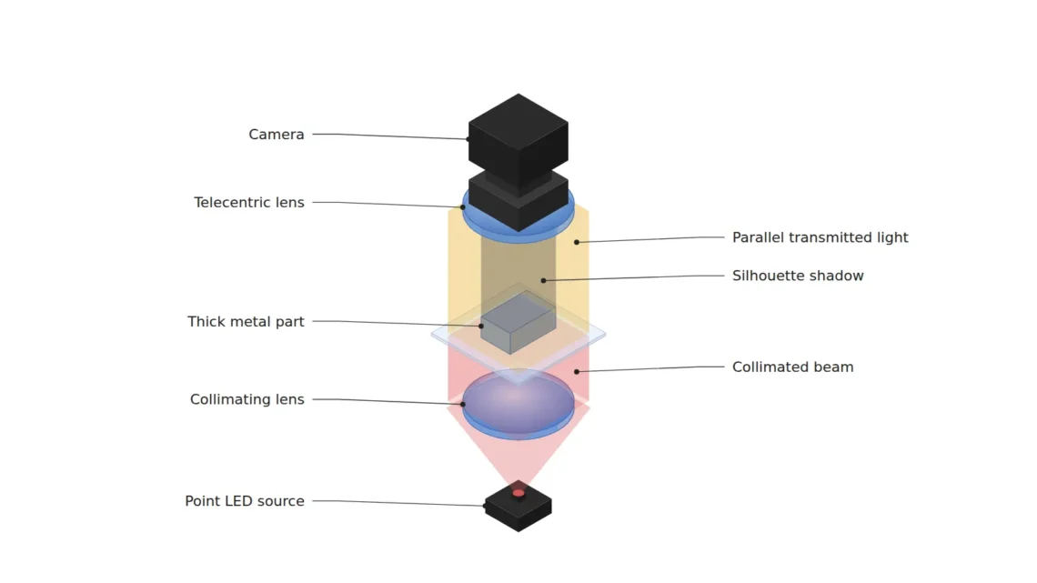
Reason. A collimated backlight places a small emitting area at the focal position of a collimator lens so that the rays are aligned parallel to the optical axis. The remaining divergence half-angle is then set roughly by emitting-area diameter ÷ (2 × collimator focal length). Because the tilt of the rays itself becomes small, the upper bound of the transition zone from the previous section, t × tanθ, shrinks by the same amount. Since a telecentric lens receives chief rays parallel to the optical axis, when the illumination is aligned in the same direction the two optical systems lock onto one axis.
Example. Placing an LED with an effective emitting diameter of 1 mm behind a collimator with a focal length of 100 mm gives a divergence half-angle of 0.5 ÷ 100 = 5 mrad, about 0.29°. For the same 3 mm thick part, the upper bound of the transition zone drops to 3 mm × 0.005 = 15 µm, about 1.5 px. Compared with the 7.6 px of the diffuse backlight, that is about one fifth. Also, subtracting the divergence half-angle of 0.29° from the lens acceptance half-angle of 1.43° leaves about 1.1°, and this value becomes the approximate upper limit of the installation tolerance for backlight tilt. Tilting beyond this range shows up immediately as vignetting that darkens one side of the image.
Point. A collimated backlight is a component designed so that the illumination side does not use up the angular margin of the rays first within the acceptance angle of the lens. A specification sheet that does not state the ratio of divergence angle to acceptance angle as a number is not yet a finished specification sheet.
With the same part and the same lens, changing only the divergence angle of the illumination shrinks the edge transition zone from 7.6 px to 1.5 px.
3. A Sub-Pixel Edge Holds Only on the Profile the Illumination Creates
Point. The precision of sub-pixel edge detection is determined, before the algorithm, by the symmetry and slope of the edge profile.
Reason. A sub-pixel edge is found by interpolating, between pixels, the maximum of the brightness gradient or the 50% point between background and part brightness. This calculation stands on the premise that the profile is a narrow, symmetric step. If the transition zone is wide, over 7 px, and asymmetric, the gradient maximum moves with the side-wall reflectance, and the 50% point also wobbles along with the background brightness. Repeatability may look good, but a deviation from the true value, that is, a systematic error, remains. Software image processing alone cannot turn this asymmetry back into the original step.
Example. After narrowing the transition zone to about 1.5 px with a collimated backlight, computing the gradient with a σ = 1.0 px Gaussian derivative and fitting a parabola to the three points around the maximum lets the edge position be determined between pixels. Adding a caliper 20 px wide along the edge direction and averaging the row-by-row results then reduces the random noise component. The wavelength must be considered as well. With a 460 nm blue source, the diffraction-limited resolution (0.61λ/NA) of an NA 0.025 lens is about 11.2 µm, about 1.1 px, and the diffraction blur is smaller than with a red source, so the edge slope becomes steeper.
Point. Before adjusting the parameters of a sub-pixel algorithm, plot the edge profile created by the illumination once. If the profile is asymmetric, the thing to adjust is not the algorithm but the backlight.
4. Core Framework — Matching Table
| Category | Item | Specification / Parameter | Basis & Notes |
|---|---|---|---|
| ① Minimum defect size | Outer edge chip (missing material) | 40 µm or more | Design assumption. Occupies about 4.1 px at 9.9 µm/px |
| ① Minimum defect size | Outer burr (protrusion) | 30 µm or more | Design assumption. About 3.0 px, at the boundary of the detection floor |
| ① Minimum defect size | Dimensional tolerance deviation | 10 µm or more | Design assumption. About 1.0 px, so judged by sub-pixel measurement, not by defect detection |
| ② Optical setup | Illumination | Parallel-light (collimated) backlight, 460 nm blue | Emitting diameter 1 mm, divergence half-angle about 0.29° (calculated value) |
| ② Optical setup | Collimator | Focal length 100 mm | 0.5 mm ÷ 100 mm = 5 mrad (calculated value) |
| ② Optical setup | Lens | Object-side telecentric 0.35×, NA 0.025 | Design assumption. Acceptance half-angle about 1.43°, diffraction limit about 11.2 µm |
| ② Optical setup | WD (working distance) | 110 mm or more must be secured | Based on the lens design WD. Verify by measurement including the part feeding mechanism and backlight height |
| ② Optical setup | Sensor & FOV | 2448 × 2048 px, 3.45 µm pixels / FOV about 24.1 mm × 20.2 mm | 3.45 ÷ 0.35 ≈ 9.9 µm/px (calculated value) |
| ③ Algorithm | Edge gradient | σ = 1.0 px Gaussian derivative | Presumes a transition zone of about 1.5 px |
| ③ Algorithm | Sub-pixel interpolation | Parabola fit to 3 points around the gradient maximum | Apply after confirming profile symmetry |
| ③ Algorithm | Caliper | 20 px wide along the edge direction, row results averaged | Purpose: reduce random noise |
| ③ Algorithm | Acceptance criterion | Repeat measurement 3σ ≤ 2 µm (about 0.2 px) | Design target. Verified by re-placing the same part 30 times |
Table implication. At 9.9 µm/px, a 40 µm chip occupies about 4.1 px and a 30 µm burr about 3.0 px, barely satisfying the shape detection condition. With a diffuse backlight, by contrast, the upper bound of the edge transition zone of a 3 mm thick part would be about 7.6 px, wider than the defect to be detected itself. Only after the collimated light reduces this to about 1.5 px does a 30 µm burr become distinguishable from edge blur, and the 0.2 px repeatability needed to judge a 10 µm tolerance also becomes a realistic target.
5. When the Opposite Approach Wins
- Targets with almost no thickness, such as thin sheet or film: t × tanθ itself is small, so even with a diffuse backlight the transition zone stays around 1 px. A diffuse backlight, which is easy to install and has a wide tilt tolerance, is more economical.
- Conventional lens configurations with a large FOV: With a non-telecentric lens the chief rays at the image periphery are tilted, so a collimated backlight darkens the periphery. In this case a diffuse backlight that supplies wide angles is the right choice.
- Inspections that must see the surface contour or the side-wall shape itself: Collimated light deliberately erases side-wall information, so seeing the chamfer of a side wall or the height of a burr requires reflected illumination or side-view imaging.
The brightness distribution of the transition zone varies greatly with the machining state and gloss of the side wall, so the actual error difference between the two approaches cannot be confirmed before sample testing.
Field Note
When I took on dimensional inspection of metal pins on a high-speed assembly line, I ran into a problem where the difference between the caliper value and the vision value changed even its direction from lot to lot. At first I tried to match it with an offset correction, but when I extracted the edge profile row by row, the shape of the transition zone was clearly different in lots with different side-wall gloss. Only after replacing the diffuse backlight with collimated light of a divergence half-angle around 0.3° did the profile become close to symmetric, and after that I set the sub-pixel parameters again. There was also a time I left the backlight installed at a tilt of a little over 1° and one side of the image went dark, which roughly matched the calculated tilt tolerance. Still, results can differ when the part material changes, so even now I check the profile first whenever the lot changes.
Field Checkpoints
- Is a WD of 110 mm or more secured by actual measurement? — Measure from the lens front end, including the part feeding mechanism and backlight height.
- Have the material, gloss and reflectance of the target side wall been checked first? — A side wall mixing sheared and fractured zones produces a different transition zone in each region.
- Is the backlight divergence half-angle sufficiently smaller than the lens acceptance half-angle? — Calculate it from the emitting diameter and collimator focal length and write it in the specification sheet.
- Is the backlight tilt within the tolerance (acceptance half-angle − divergence half-angle)? — Check by comparing the brightness of the four corners of the FOV.
- Has the edge profile been plotted to confirm symmetry? — Adjusting the sub-pixel parameters comes after that.
- Is the repeatability (3σ) of 30 re-placements of the same part measured again at every lot change?

Noctvision
A machine vision engineer who fits cameras, lenses, lighting, and image-processing algorithms together for a living. Years spent on continuous production lines, vibration, heat, and dust included, working through diffuse reflection, contrast, and resolution differences too fine for a spec sheet to capture inform every post here, closing the gap between theory and the shop floor. Off duty, that same eye for light and lenses goes into repairing fully mechanical vintage film cameras.


You May Also Like
Why Does One Lighting Angle Decide OCR Read Rates on Molded Characters? — Low-Angle Ring Illumination and Quadrant Lighting Calculated from Character Height and Stroke Spacing
How to Handle Imaging on Highly Reflective Surfaces