Flat-Field Correction Gain Amplifies Noise Along with Uneven Light
LIGHTING
Correction gain brings back the brightness of the corners but amplifies the noise with it, so in a corner getting 60 % of the light, the chance of noise crossing the same decision line becomes 30 times higher.
For a 5 MP camera viewing a white molded housing 120 mm across, I calculated the correction gain and noise, the share the lens takes and the number of reference frames to average.
About 13 min read
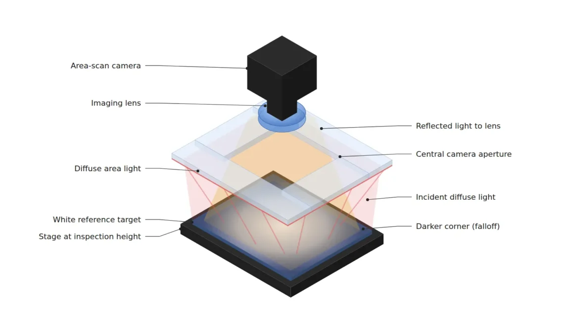
The idea that one shot of a white reference and a gain on every pixel finishes off uneven lighting looks convincing once you see the corrected image. Light a matte white ABS housing 120 mm across, and most of its reflection is diffuse reflection1 that scatters light evenly in every direction, so the image brightness copies the distribution of the light almost exactly. When the emitting surface of the light does not cover the whole field, the corners get darker than the center, and flat-field correction2 multiplies those corners by a gain to stretch the image flat.
What a stretched image misses is noise. A stain with 5 % contrast that is caught easily in the center gets buried in noise at the corners and passes, and lowering the decision line then piles up false rejects at the corners only. Since the escapes cluster in particular spots of the image, it takes a long time before the lighting is found to be the cause, and by then the cost of sorting the shipped lots has already built up.
The question is how much of the uneven lighting the correction gain really erases. I treat the gain as a number that measures the state of the lighting, not as an eraser. The calculations assume a 5 MP camera with 2,448 × 2,048 px and 3.45 μm pixels, fitted with a 25 mm lens viewing 120 mm by 100 mm. One pixel covers 49.0 μm, and the WD3 from the lens principal plane to the housing is about 380 mm.
What the flattened image hides
The correction usually takes the form (raw − dark frame) ÷ (reference − dark frame) × reference mean. A dark frame4 taken with the lens cap on removes the floor value of the sensor, and the white reference image divides out the share of light each pixel receives. A corner receiving only 60 % of the light of the center gets multiplied by a gain of 1 ÷ 0.6 = 1.67.
The same thing happens in the corners as when you brighten a dark photo on a phone and a grainy speckle rises with it. Gain scales signal and noise alike by the same factor, so the corrected image is flat only in its average, while the width of the noise differs from place to place. The middle graph in the figure below shows that shape.
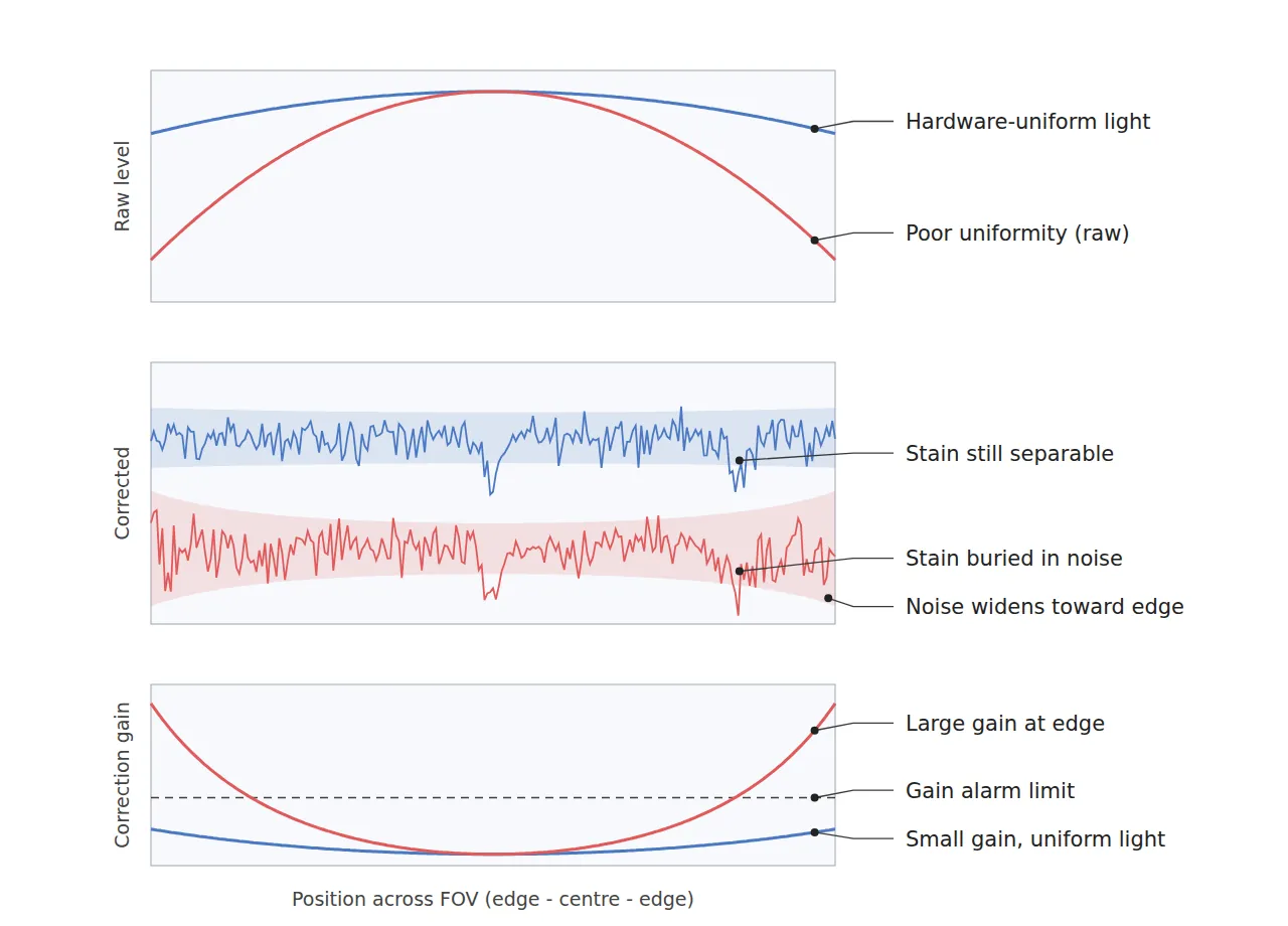
When the lighting is uneven, the corner gain crosses the alarm line, as the lower curve in the figure shows, and in the middle graph the same stain stands above the noise on one side and is buried in it on the other. Put one decision line over the whole image, and two inspections with different detection chances end up running inside a single frame, one in the center and one in the corners. One decision line cannot guard both.
A gain of 1.67 raises corner noise to 1.29 times
In numbers it goes like this. Shot noise5, the wavering in the number of light particles, follows the square root of the signal, so the signal-to-noise ratio6 of a corner receiving 60 % of the light is already √0.6 = 0.77 of the center before correction. Even after the 1.67 gain of the flat-field correction restores the average, the corner noise stays at 1 ÷ √0.6 = 1.29 times the center noise.
Say the decision line sits at four times the standard deviation7 of the center noise, the 4σ point. Assuming normally distributed noise, the chance that one center pixel crosses the line on noise alone is 0.0032 %. In the corner, the same line sits at 3.10 times the corner noise, so the chance jumps to 0.097 %, 30 times higher. Thirty times is no small gap. Raise the line to suit the corners, and the stains caught in the center start to slip through instead. How good pixels turn into defects when the light dims is calculated separately in what happens when the light dims by 5 %.
1.67times
the correction gain on a corner getting 60 % of the light
1.29times
corner noise after correction, against the center
30times
chance of noise crossing the same 4σ line, against the center. Normal distribution assumed
With an 8-bit image, the gray levels become a problem too. A 5 % stain on a center background of 200 levels makes a 10-level difference, but in a corner at 120 levels it is 6 levels. After correction the difference looks like 10 levels again, yet the steps between levels open to 1.67 apart and empty slots appear in the histogram8. My standard is to switch to 12-bit output whenever the gain exceeds 1.2; at 12 bits the same stain in the corner spans 96 levels, leaving less room for the empty slots to interfere with the decision.
The 8 % the lens takes first
It seems enough to make the lighting even, but the lens takes its share first. Light through a lens falls off roughly as cos⁴θ with the angle θ from the optical axis; this is the cosine fourth law9, and stopping down does not remove it.
In this setup the distance to the corner of the field is √(60² + 50²) = 78.1 mm, and at an object distance of 380 mm the angle to the corner is 11.6°. Since cos⁴(11.6°) = 0.92, the corner is 8 % darker than the center even under perfectly even lighting. The lens makes that gap on its own. The value for a real lens has to be checked against the relative illumination curve from the lens maker, but this 8 % is a share that the uniformity figure in a lighting catalog does not include.
Set a uniformity target of ±10 % around the mean, and the darkest spot is 0.9 of the mean, the brightest 1.1, with a ratio of 0.82 between them. The lens takes 8 % at the corners first, so the margin left for the light is narrower than it seems; my standard is to make the emitting surface at least 30 % larger than the field on each side and, if that still falls short, to offset the lens falloff with a layout that raises the output slightly toward the corners. Hold this target, and the maximum correction gain stays at 1 ÷ 0.9 = 1.11, the corner noise at 1.05 times, and the chance of noise crossing the same 4σ line at 2.3 times the center.
Noise in the reference is copied into every image
The reference image of a flat-field correction is a measurement multiplied into every inspection image that follows, not a setting you take once and forget. The noise and surface texture in a single reference image turn into inverse gains and get stamped as a fixed pattern into the same spot of every later image.
When taking the reference
one shot of a white board seems enough to capture the shape of the light.
Adding up the noise
a correction built from one shot raises the noise of every later image to 1.41 times. It takes an average of 16 shots to bring it down to 1.03 times.
With a single reference shot, the noise of the corrected image is the original noise plus a fixed pattern of the same size, √2 = 1.41 times in all. Averaging 4 shots brings it down to 1.12 times, and 16 shots to 1.03 times, almost back to the original noise. That is enough. My approach would be to make 16 the standard and to shift the reference board by a few mm between shots so its texture does not stay behind as a pattern.
The order of acquisition changes the result as well. Once the light and camera reach operating temperature, 16 dark frames are averaged with the lens cap on, at the same exposure and gain as inspection. Next, a white reference is placed at the height of the inspected surface and 16 shots are averaged near 70 to 80 % of full scale without saturation, and finally the maximum of the gain map is recorded. If that value exceeds the design limit of 1.25, the correction is not applied and a lighting check alarm goes up.
That turns the gain map into an instrument that records the state of the lighting, before it is a tool that fixes images. A limit of 1.25 means the darkest spot is at 80 % of the mean, and there the chance of noise crossing the same decision line is 5.5 times that of the center. A gain-map maximum that creeps up over several weeks is the earliest sign of lighting wear or contamination, so I log this number in the same place as the inspection recipe. How an aging light wears down the decision line is calculated separately in LED light output degradation and temperature drift.
Specs that protect a 150 μm black dot and a 5 % stain
Gather the lighting, lens and correction parameters for black dots, stains and scratches on one page, and it comes out as below. Pixel counts use one 49.0 μm pixel.
| Item | Value | Condition and basis | In plain words |
|---|---|---|---|
| ① Minimum defect size · black foreign dot | 150 μm diameter = 3.06 px (49.0 μm/px) | 120 mm across ÷ 2,448 px; the first defect lost when noise widens | Just over three pixels, so corner noise decides |
| ① Minimum defect size · low-contrast stain | 1,000 μm diameter (20.4 px), 5 % contrast | contrast limits more than size, 6 levels in an 8-bit corner | Plenty of size, little contrast |
| ① Minimum defect size · surface scratch | 2,000 μm long = 40.8 px | linear defect, directional filter | Seen as a long continuous line |
| ② Optical setup · surface and light | matte white ABS, large diffuse area light, emitting surface at least 30 % larger than the field on each side | image uniformity ±10 % of the mean, darkest-to-brightest ratio 0.82 or more | The light must be comfortably larger than the field |
| ② Optical setup · camera and lens | 5 MP (3.45 μm), 25 mm, 12-bit output | corner angle 11.6°, cos⁴θ = 0.92 (8 % from the lens alone) | The lens takes 8 % at the corners first |
| ② Optical setup · WD | about 380 mm (from principal plane) | measured including interference between the area light housing and camera bracket | Secure it with the light housing height included |
| ③ Algorithm parameters · correction reference | average of 16 dark frames and 16 white reference shots | noise after correction 1.03 times (1.41 times with one shot) | Average several reference shots |
| ③ Algorithm parameters · gain limit | stop correcting and raise an alarm above 1.25 | nominal maximum 1.11 with ±10 % design; 1.25 means the darkest spot at 80 % | A large gain means checking the light |
| ③ Algorithm parameters · detection threshold | 4σ deviation from the local background, σ estimated per 8 × 8 zone | reflects the position-dependent noise in the decision line | Use a line matched to the local noise |
| ③ Algorithm parameters · reference refresh | whenever the light or lens changes, and once a week | log the trend of the gain-map maximum | Retake it on a schedule |
Reading the first row beside the gain-limit row shows that the key to protecting a 3.06-pixel black dot is the uniformity of the lighting more than the correction parameters. Hold ±10 % in hardware, and the nominal gain stays at 1.11 with room to absorb lighting wear before the 1.25 alarm, whereas in a setup that fills a 60 % corner with gain, the black dot is the first thing lost in the noise. Setting the threshold by zone σ only evens out the false rejects; it cannot pull a buried dot back out.
Setups where correction alone is enough
On the other hand, some setups clearly get by with gain correction alone. Small parts with a narrow field have small corner angles, so the lens falloff is slight and the emitting surface easily covers the field; a general-purpose light plus flat-field correction keeps the gain small. If the defect contrast exceeds 30 %, as with a black particle on a white surface, the detection margin survives even a noise boost from a gain of about 1.5, and changing the light may cost more.
Materials that mix diffuse and specular reflection10, such as glossy resin or machined metal, reflect differently from the white reference, so a gain built on the reference works in a different shape on the sample. A slight tilt of the sample changes the shape of the shading itself, so how well correction works on such surfaces cannot be guaranteed before a sample test.
The person who turns gain-map numbers back into lighting specs is the machine vision engineer on site. For someone starting to learn, I recommend placing white paper under a desk lamp, photographing it with a phone and zooming into the corners, to compare with your own eyes how the speckle grows wherever the brightness has been pulled up. From the equipment budget side, a light with a larger emitting surface costs more, but a fair comparison sets that cost in the same table as the cost of sorting lots that escaped at the corners. This article explains technology and is not investment advice. See our Disclaimer.
Field Note
If the gain-map maximum sits around 1.6, I look at the emitting surface of the light first and leave the corrected image for later. By the numbers of this setup, that spot receives only a little over 60 % of the light, and the chance of noise crossing the same decision line there is close to 30 times that of the center. If the emitting surface turns out smaller than the field, it gets enlarged or its distance adjusted, and the reference is retaken as an average of 16 shots to see whether the gain comes back under 1.2.
Field Checkpoints
With the gain-map maximum in hand, use the questions below to turn the lighting and correction into spec-sheet sentences.
- Inside the WD of about 380 mm (25 mm lens, from the principal plane), do the area light housing and the camera bracket stay clear of each other? (distance from the lens front from the lens drawing)
- Have you first confirmed whether the surface is matte and scatters evenly, or glossy with a specular share? (it decides whether reference correction works)
- In the raw image, is the ratio of the darkest spot to the brightest spot 0.82 or more? (the hardware check for a ±10 % target)
- Were the dark frames and white reference each taken as a 16-shot average at operating temperature?
- Is the gain-map maximum 1.25 or below, and is its trend being logged?
- Is the detection threshold set by zone σ instead of one value for the whole image? (so false rejects do not pile up in the corners)
Frequently Asked Questions
Wouldn’t a longer exposure, instead of gain, reduce the corner noise?
It would. A longer exposure really sends more photons into the corners, so the SNR rises. The center brightens along with them, though, and reaches saturation first, so with the center held at 80 % of full scale, the only way to raise corner SNR to the level of the center is to change the distribution of the light after all. Think of exposure as the knob for the brightness of the whole image and the light layout as the knob for the ratios inside it.
Can any white board serve as the white reference?
It has to have an even surface texture and scatter light evenly in every direction. A board with coarse texture stamps that texture into every image as a fixed pattern, and a glossy board forms reflection spots that depend on the light position and punch holes in the gain map. My approach would be to treat the reference as a consumable that gets dirty and discolored, and when the gain-map maximum rises for no clear reason, to clean or replace the reference before suspecting the light.
Glossary
- [1] Diffuse reflection diffuse reflection
Reflection in which light scatters evenly in every direction from a rough surface. It looks about equally bright from any direction. ↩ - [2] Flat-field correction flat-field correction
A correction that sets a gain for every pixel from an image of a white reference, flattening the image brightness. It is also called shading correction. ↩ - [3] WD working distance
The distance from the lens to the inspected surface. The values here are thin-lens numbers from the lens principal plane, and the actual clearance from the lens front is checked on the lens drawing. ↩ - [4] Dark frame dark frame
An image taken with the light blocked at the same exposure as inspection. It holds, for every pixel, the floor value the sensor gives out even without light. ↩ - [5] Shot noise shot noise
Noise from the number of light particles reaching the sensor varying slightly every time. Its size follows the square root of the signal. ↩ - [6] Signal-to-noise ratio signal-to-noise ratio, SNR
The size of the signal divided by the size of the noise. Where it is low, even the same defect is hard to tell from noise. ↩ - [7] Standard deviation standard deviation, σ
A width that describes how far values scatter around their mean. If the noise is normally distributed, a value falls more than 4σ from the mean about once in thirty thousand. ↩ - [8] Histogram histogram
A bar graph that counts the pixels of an image by brightness. A large gain leaves empty slots between the bars. ↩ - [9] Cosine fourth law cos⁴ law, natural vignetting
The natural falloff in which the brightness of light through a lens drops with the fourth power of the cosine of the off-axis angle. Stopping down does not remove it. ↩ - [10] Specular reflection specular reflection
Reflection in which light bounces off a smooth surface in one direction only, at the same angle it came in. A slight tilt of the sample changes its brightness a lot. ↩
References
- Formulas: correction = (raw − dark frame) ÷ (reference − dark frame) × reference mean, gain = 1 ÷ relative brightness, noise ratio after correction = 1 ÷ √relative brightness, line-crossing probability = Φ(−4 ÷ noise ratio), noise after averaging N reference shots = √(1 + 1/N), relative illumination ≈ cos⁴θ, θ = atan(corner distance ÷ object distance)
- Assumptions: 5 MP camera (2,448 × 2,048 px, 3.45 μm), 25 mm lens, 120 mm × 100 mm field, corner relative brightness 0.6, decision line at 4σ, normally distributed noise, 8-bit center background 200 levels and corner 120 levels, stain contrast 5 %
- Vignetting (natural vignetting and the cos⁴ law), Wikipedia. en.wikipedia.org/wiki/Vignetting
Related reading — When an LED Light Dims, Yesterday’s Threshold Misses Today’s Defect · Why Are the Ends of a Line Scan Image Dark? · When the Light Dims by 5 %, How Many Good Pixels Turn Into Defects?

Noctvision
An engineer who has handled mechanical design and project management for production equipment since 2005. Here I work through the cameras, lenses and lighting that go into equipment with formulas and public data, and record the assumptions and sources alongside the numbers.


You May Also Like
How Strongly Cross-Polarization Suppresses Glare Depends on the Lighting Angle
Moving Parts Are Frozen by How Long the Light Stays On