Can Correction Gain Erase Uneven Illumination? — The Limits of Flat-Field Correction and Designing Uniformity First
LIGHTING / ALGORITHM
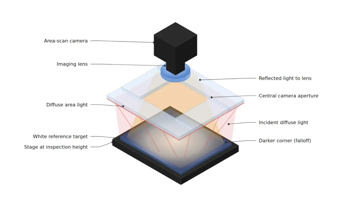
The most common image in large-FOV appearance inspection is a frame that is bright in the center and grows darker toward the corners. When the emitting surface of the illuminator does not fully cover the FOV, or when the lens’s own peripheral light falloff is added on top, the corners become tens of percent darker than the center. Many sites settle this problem with a single line of flat-field (shading) correction: capture a white reference target and multiply each pixel by a gain to flatten the frame.
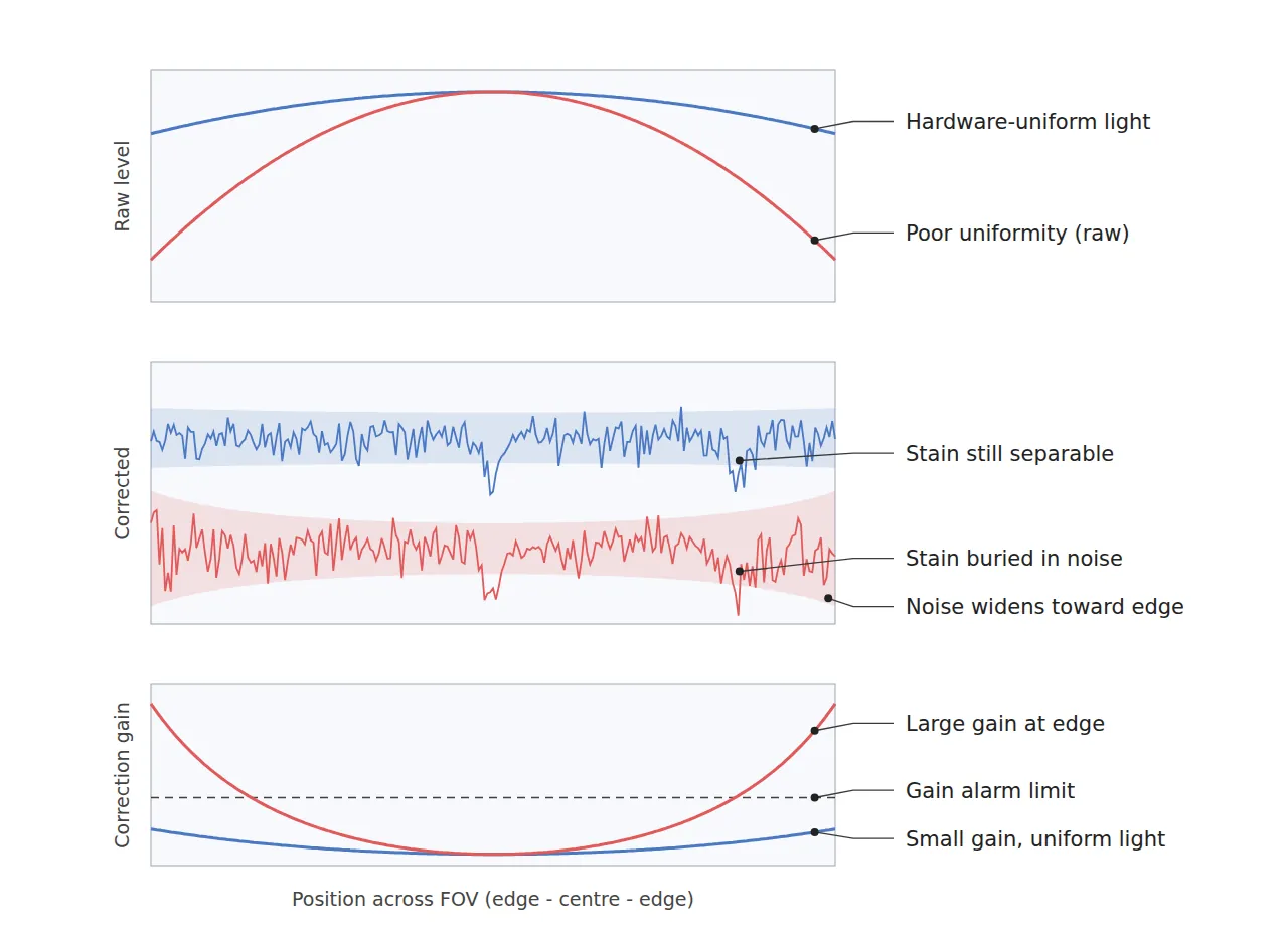
After correction, the image certainly looks flat. But the gain multiplied into the corners amplifies noise by the same factor as the signal. A stain with 5 % contrast that was caught reliably in the center gets buried in noise fluctuation at the corners and passes, and if the threshold is lowered instead, false detections pile up only in the corners. Defect escapes appear concentrated at specific positions in the frame, and the fact that the cause is the illumination surfaces only much later. By then, the sorting cost of escaped lots and the customer claims have already been incurred.
The order of the solution is clear. First bring illumination uniformity within the design target with hardware, and limit flat-field correction to a tool that trims only the remaining residual. This article works through, in order, the relationship between correction gain and noise amplification, how to allocate the uniformity budget including the lens, and the procedure for acquiring the white reference target.
Flat-field correction only flattens the mean brightness of the frame; it cannot flatten the signal-to-noise ratio.
1. The Larger the Correction Gain, the More Noise Grows by the Same Factor
Point. The essence of flat-field correction is per-pixel gain multiplication, and the gain does not distinguish signal from noise.
Reason. The correction formula generally takes the form “(raw − dark frame) ÷ (reference − dark frame) × reference mean”. A corner that receives only 60 % of the center’s light is multiplied by a gain of about 1.67. Yet the shot noise of the raw corner signal is proportional to the square root of the signal, so the corner SNR has already dropped to √0.6 ≈ 0.77 of the center before correction. The gain restores the mean, but this ratio of 0.77 remains unchanged, and read noise and quantization error are actually magnified by 1.67.
Example. If the center background is 200 gray levels in an 8-bit image, a stain with 5 % contrast creates a difference of 10 gray levels. If the corner background is 120 gray levels, the same stain creates a difference of 6 gray levels. After correction this difference again looks like 10 gray levels, but the gray-level spacing has widened to 1.67 units, leaving empty codes in the histogram, and the noise width has widened along with it. Applying a single threshold across the frame effectively runs two inspections with different detection probabilities, center and corner, inside one frame.
Point. The maximum correction gain should therefore be treated not as a question of “whether correction works” but as a design limit on how much difference in detection probability by position is acceptable.
2. The Uniformity Budget — The Share the Lens Takes First
Point. The illumination uniformity target should be allocated not as a specification of the illuminator alone, but on a frame basis that combines illumination + lens + sample reflection.
Reason. A lens has peripheral light falloff that follows the cosine-fourth law. The relative illuminance at half field angle θ is roughly proportional to cos4θ. However uniform the illuminator is made, the lens shaves off a certain fraction at the corners first, so promising frame uniformity based only on the uniformity figure in the illuminator catalog overruns the budget.
Example. In this article’s design assumption of a 120 mm × 100 mm FOV at an object distance of about 380 mm, the half-diagonal distance to the corner is about 78 mm and the half field angle is about 11.6°. Since cos4(11.6°) ≈ 0.92, the lens alone makes the corners about 8 % darker than the center (a calculated value; for an actual lens, confirm with the manufacturer’s relative illumination curve). If the frame uniformity target is set to ±10 % of the mean, the margin left for the illuminator is smaller than expected. That is why the emitting surface should be made at least 30 % larger than the FOV on each side, or arranged with slightly higher output toward the corners to offset the lens falloff. Materials dominated by diffuse reflection, such as a matte white molded surface, are relatively easy to predict, but on glossy surfaces the shape of the shading itself changes with the tilt of the sample, so this cannot be confirmed before sample testing.
Point. Holding the ±10 % target keeps the maximum correction gain at 1 ÷ 0.9 ≈ 1.11, and limits the SNR loss in the darkest zone to about √0.9 ≈ 0.95. Hardware uniformity is the design variable that sets the upper limit of the correction gain.
3. White Reference Acquisition — Reference Noise Is Copied into Every Image
Point. The reference image is not a setting captured once and forgotten, but a measurement that is multiplied into every inspection image that follows.
Reason. Noise and surface texture mixed into the reference image are converted into reciprocal gain during correction and imprinted as a fixed pattern at the same positions in every subsequent image. If the noise of a single reference frame is σ, the noise of an N-frame average falls to σ/√N. In other words, the acquisition quality of the reference becomes part of the noise floor of the corrected image.
Example. The practical procedure can be organized in the following order. First, bring the illumination and camera to operating temperature. Second, average 16 dark frames with the lens cap on, at the same exposure and gain as inspection. Third, place a uniform diffuse white reference target at the same height as the inspection surface and average 16 frames at 70 to 80 % of full scale without saturation (averaged noise σ/4). Fourth, average while shifting the reference target a few mm at a time so that its surface texture is not imprinted as a pattern. Fifth, record the maximum value of the correction gain map, and if it exceeds the design limit (1.25 in this article), do not apply the correction and raise an illumination check alarm.
Point. Reference acquisition should be managed as part of the inspection recipe, and the trend of the gain map maximum becomes the earliest indicator of illumination degradation and contamination.
Before it is a tool that fixes images, the correction gain map is an instrument that records the state of the illumination.
4. Core Framework — Matching Table
| Category | Item | Specification / Parameter | Basis & Notes |
|---|---|---|---|
| ① Minimum defect size | Black foreign particle | Diameter 150 µm or more | Design assumption. About 3.1 px at 49 µm/px |
| ① Minimum defect size | Low-contrast stain (discoloration) | Diameter 1,000 µm or more, 5 % contrast | Design assumption. About 20 px; contrast, not size, is the constraint |
| ① Minimum defect size | Surface scratch | Length 2,000 µm or more | Design assumption. Linear defect about 41 px long |
| ② Optical setup | Target material | Matte white ABS molded housing | Diffuse reflection dominant, high reflectance (design assumption) |
| ② Optical setup | Illumination | Large diffuse area light, emitting surface +30 % per side versus FOV | Target frame uniformity ±10 % of mean (design assumption) |
| ② Optical setup | Camera | 5 MP, 2448 × 2048 px, 3.45 µm pixel | Sensor about 8.45 mm × 7.07 mm |
| ② Optical setup | Lens | Focal length 25 mm, magnification about 0.070 | Corner cos4 falloff about 8 % (calculated value) |
| ② Optical setup | WD (working distance) | 350 mm or more must be secured | Thin-lens object distance about 380 mm. Measure including area light housing interference |
| ② Optical setup | FOV & pixel resolution | 120 mm × 100 mm, about 49 µm/px | 120 ÷ 2448 ≈ 49.0, 100 ÷ 2048 ≈ 48.8 |
| ③ Algorithm | Flat-field reference | 16-frame average each for dark frame and white reference | Reference noise reduced to σ/4 |
| ③ Algorithm | Correction gain limit | Stop correction and alarm above 1.25 | Design assumption. Nominal maximum 1.11 with ±10 % design |
| ③ Algorithm | Detection threshold | Deviation from local background > 4σ, σ estimated per 8 × 8 zone | Reflects the SNR difference by position in the threshold |
| ③ Algorithm | Reference re-acquisition | On illumination or lens change + once a week | Record the trend of the gain map maximum |
Table implication. At 49 µm/px, a 150 µm black particle occupies about 3.1 px and sits right at the detection floor, so when the corner gain grows to 1.67 and the noise widens, it is the first defect to be missed. By contrast, securing ±10 % uniformity in hardware keeps the nominal gain at 1.11, leaving room between it and the 1.25 alarm limit to absorb illumination degradation. Given that the lens cos4 falloff alone consumes about 8 %, the core of this table is that the uniformity budget must be set on a frame basis, not on the illuminator specification.
5. When the Opposite Approach Wins
- Small parts with a narrow FOV: The half field angle is small, so lens falloff is negligible, and the emitting surface easily covers the FOV. Adding only software correction to general-purpose illumination keeps the gain small.
- Cases where defect contrast is very large: When contrast is 30 % or more, such as a black particle on a white surface, detection margin remains even with noise amplification at a gain of about 1.5. Replacing the illumination may cost more.
- Line-scan configurations with only one-dimensional shading: Shading occurs along only one axis, so a one-dimensional correction table is simple and stable. Managing the gain limit is still equally necessary.
For materials where diffuse and specular reflection mix, such as glossy resin or machined metal surfaces, the reflection characteristics of the reference and the sample differ and the correction effect changes accordingly, so this cannot be confirmed before sample testing.
Field Note
When I reviewed appearance inspection of white molded covers on a high-speed assembly line, stain escapes were concentrated only in the lower-right corner of the frame. I suspected the algorithm, but when I printed the gain map, the correction gain in that corner had climbed close to 1.6, and as I recall the cause was an area light whose emitting surface had been installed smaller than the FOV. After enlarging the emitting surface and re-acquiring the reference as a 16-frame average, the gain came down to within 1.2 and the corner concentration visibly decreased. The same effect cannot be expected on every line, but since then I have made a habit of checking the gain map maximum first.
Field Checkpoints
- Is a WD of 350 mm or more secured by measurement — verify including interference from the area light housing and the camera bracket.
- Has the surface material and reflectance of the target been confirmed first — the validity of reference-based correction depends on whether reflection is diffuse or mixed with specular and scattered components.
- In the raw image before correction, is the ratio of the darkest zone to the brightest zone 0.82 or more — this is the hardware check value for the ±10 % target (0.9 ÷ 1.1).
- Were the dark frame and white reference each acquired as a 16-frame average at operating temperature.
- Is the maximum of the correction gain map 1.25 or less, and is its trend being recorded.
- Is the detection threshold set by per-zone σ rather than a single value for the whole frame.

Noctvision
A machine vision engineer who fits cameras, lenses, lighting, and image-processing algorithms together for a living. Years spent on continuous production lines, vibration, heat, and dust included, working through diffuse reflection, contrast, and resolution differences too fine for a spec sheet to capture inform every post here, closing the gap between theory and the shop floor. Off duty, that same eye for light and lenses goes into repairing fully mechanical vintage film cameras.


You May Also Like
Can’t You Catch Color Differences Without a Color Camera? — Building PCB Solder Mask, Silkscreen and Copper Pad Contrast with a Mono Camera and Wavelength Selection
How Do You Inspect a Film You Cannot See? — Catching PCB Conformal Coating Gaps with UV Fluorescence Lighting and Long-Pass Filters