Automotive Part Appearance Inspection: Lighting Design Comes First
In last August’s newsletter from the Korea Machine Vision Industry Association, I came across news that an AI vision system for automotive-part appearance inspection would be shown at ‘Automation World Vietnam 2026’ in Hanoi starting September 9. It’s welcome news, but every time I come across a system like this in the field, my eyes always go to the same starting point first: how the inspection target’s surface is receiving the light.
Automotive parts mix materials with widely different reflectivity — painted metal surfaces, chrome-plated components, injection-molded trim — all within a single line. Ignore this difference and apply uniform diffuse lighting across the board, and a micro-scratch or dent defect gets buried in the background contrast, recorded by the camera sensor as an almost uniform surface. Go into mass production in this state, and defects that even a visual re-inspection would miss ship out as-is, carrying a risk of quality claims or a recall. The solution is simple: finalize a lighting design matched to the material’s reflective characteristics first, then build a two-layer structure on top of it, using an AI algorithm to reduce false detections across curvature and reflection patterns.
Why reflective characteristics by surface material need to be addressed first
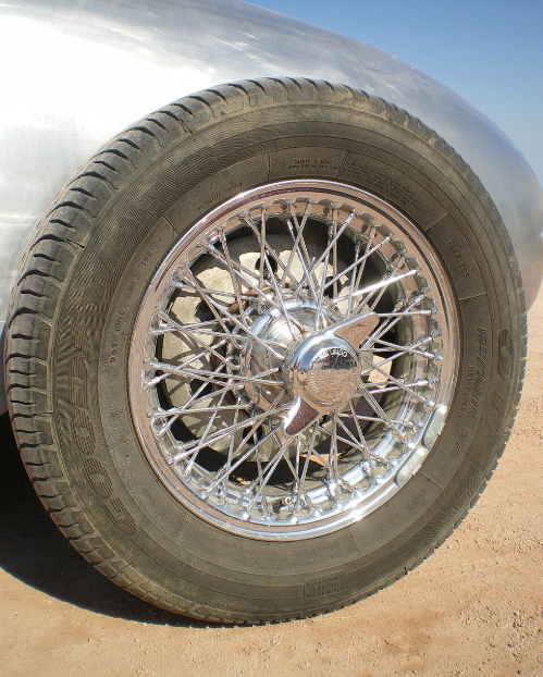
The first thing to check when designing an appearance inspection is not the algorithm, but the surface itself. Even among the same metal, a painted surface is close to semi-specular reflection, a chrome-plated part is very close to pure specular reflection, and injection-molded trim shows matte diffuse reflection. In particular, a surface with extreme diffuse-reflection variation like a chrome-plated surface has a reflection pattern that differs from part to part, so it cannot be confirmed that a specific lighting condition will work until it is verified on actual samples.
Coaxial epi-illumination vs. dark-field illumination: selection criteria by situation
For a chrome-plated part or a glossy painted surface close to pure specular reflection, coaxial epi-illumination is often favorable. Aligning the camera’s optical axis with the lighting’s optical axis makes a normal flat region reflect back uniformly bright, while a defective region with an off-angle surface — a dent, foreign matter — sends its reflected light out past the lens and shows up dark by contrast. Conversely, for a low-angle linear defect like a scratch, dark-field illumination is favorable. That said, the optimal angle of incidence varies with part curvature and plating condition, so the final angle always has to be verified on actual samples.
The AI algorithm’s role, and the limit that hardware creates
A deep-learning classification algorithm, trained on a variety of curvatures and reflection patterns, distinguishes local brightness variation from the actual texture difference of a defect, meaningfully lowering the false-detection rate even under the same optical setup. But in an image where contrast between the defective and normal regions was never secured to begin with — that is, an image where a defect is completely buried in the background by diffuse reflection — no algorithm, however sophisticated, can reconstruct information that isn’t there. Software can only perform on top of the contrast that the optical setup has already created.
| Category | Baseline |
|---|---|
| ① Minimum detectable defect size | Scratch/dent width baseline 30–80 µm (varies with part curvature and surface condition) |
| ② Optical setup | Specular surface (chrome plating, glossy paint): coaxial epi-illumination + 25–50 mm focal-length lens, WD 100–150 mm secured / Linear angled defects: dark-field illumination (low-angle incidence) + lens in the same WD range |
| ③ Algorithm parameters | Pre-set threshold for masking specular-highlight regions; tune the false/missed-detection balance point in the deep-learning defect-classification confidence range of 85% or higher |
As the table above shows, specular and diffuse surfaces each need a different lighting strategy, and the algorithm’s confidence threshold likewise has to be tuned separately to match the contrast level the optical setup produces.
Field Checkpoints
- Has the surface material (painted, chrome-plated, injection-molded) and reflectivity been distinguished in advance for each inspected part?
- When positioning the lens and lighting, is WD (working distance) secured with enough margin to shoot without lighting interference?
- Has the method suited to the defect type, coaxial epi-illumination or dark-field, been verified on actual samples?
- Has the algorithm’s confidence threshold been tuned to actual production conditions in the field, balancing false and missed detections?


You May Also Like
Detection Time Cut 65%, False Alarms Down 80%: How to Read the Two Numbers Behind Edge Fire-Detection AI
Few-Shot Anomaly Detection: Can 5 Defect Samples Stand Up an Inspection Line