Liquid Lens Autofocus: Solving the Focus Problem on High-Mix, Low-Volume Production Lines
The experience of focus subtly drifting every time a lot changes, even for parts passing through the same inspection zone, will be familiar to many. A typical case is a PCB assembly line where component height ranges 0.3–1.2mm, or injection-molded part inspection where surface height varies by hundreds of µm lot to lot depending on the gate-cutting position. A fixed-focus lens produces blur the instant an object falls outside the depth of field (DOF), and that blur drops edge contrast enough to let micro-cracks or micro foreign matter pass straight through.
One mechanical way to solve this is attaching a motor-driven focus lens, but on a line processing dozens of parts per second, the motor’s mechanical response speed itself becomes the bottleneck. Left unaddressed, missed detections from focus drift accumulate, and the result comes back as a far larger cost in customer claims and line stoppages. I have approached this problem by using an electrowetting liquid lens instead of motorized focus, cutting refocus time to within tens of ms.
What a liquid lens does differently
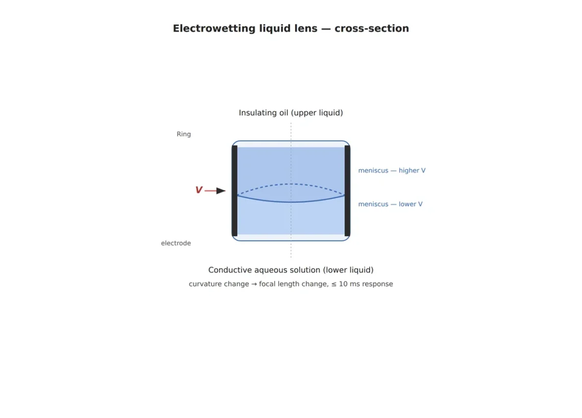
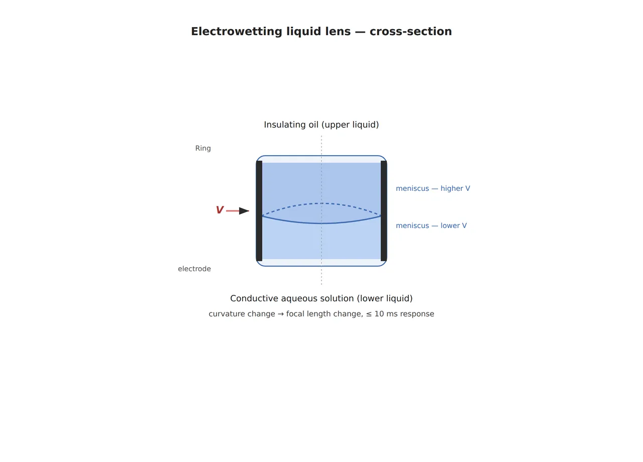
A liquid lens changes curvature by applying voltage across the interface of two liquids with different refractive indices — typically a conductive aqueous solution and an insulating oil (the electrowetting principle). Because there are no moving mechanical parts inside the lens, response speed is more than an order of magnitude faster than mechanical autofocus, and repeat focus precision stays stable. That said, this approach isn’t a universal fix. Given the lens’s own numerical aperture (NA) and the properties of the liquid interface, a telecentric fixed-focus lens is still favorable for ultra-high-magnification, ultra-precision dimensional measurement (sub-µm gauge measurement), and in heavily vibrating environments, minute fluctuation of the liquid interface can affect image stability — this is an area that cannot be confirmed before sample testing with the actual vibration spectrum applied.
In summary, liquid-lens autofocus shows its strength in (1) high-mix, low-volume lines where workpiece height changes lot to lot, (2) high-speed transfer lines requiring dozens of refocus cycles per second or more, and (3) tight inspection zones where mechanically securing motor stroke is difficult. Conversely, if the goal is nanometer-to-sub-µm absolute dimensional measurement, a fixed-magnification telecentric lens remains the standard choice.
Start by confirming the inspection target’s surface and reflectivity
Before attaching a liquid lens, what I always confirm first is the target’s surface material and reflectivity. On a highly glossy metal surface like a PCB solder joint, specular reflection highlights can be captured differently frame to frame even within a liquid lens’s short focus-shift window, so I first validate the combination with coaxial epi-illumination. Conversely, on a surface dominated by diffuse reflection, such as a matte injection-molded part, the contrast loss from focus shift is felt more strongly, so the liquid lens’s refocus speed itself — more than the lighting angle — governs the inspection cycle. As always, numerically guaranteeing the defect detection rate on a heavily diffuse-reflective material cannot be confirmed before sample testing — that same principle applies here as well.
Core framework: minimum defect size, lighting/lens spec, algorithm parameters
The matching table below is organized around two inspection targets: PCB solder joints (glossy metal) and injection-molded part exteriors (matte plastic). In an actual line deployment, lighting conditions must be re-tuned to match the target’s reflectivity.
| Item | PCB solder joint inspection | Injection-molded part exterior inspection |
|---|---|---|
| ① Minimum detectable defect size | 30µm (solder bridge, void) | 50µm (scratch, sink mark) |
| ② Optical setup — lighting | Coaxial epi-illumination + low-angle dark-field assist, illuminance 4,000–6,000lx | Dome diffuse illumination, illuminance 2,000–3,000lx |
| ② Optical setup — lens/WD | Liquid lens (electrowetting, focus response ≤10ms) + fixed-magnification lens combination, WD 80mm secured | Liquid lens alone, variable focus range ±5D, WD 150mm secured |
| ③ Algorithm parameters | 3-frame focus-stack fusion followed by Sobel edge detection, threshold binarization 128±15 | Local contrast normalization + blob analysis, minimum blob area 40px |
Takeaway: as the table shows, even with the same liquid lens, glossy metal (PCB) requires an algorithm design that offsets specular-reflection noise arising during focus shift through multi-frame fusion, while on matte plastic, contrast normalization has a much greater effect on detection rate. Securing WD is an essential precondition in both cases, to avoid interference between the liquid lens module’s drive wiring space and the lighting angle.
A technology lineage seen through patents
Liquid-lens-based machine vision autofocus is already a mature technology axis with a substantial patent lineage. Notably, Cognex Corporation’s US8487228B2 ("System for adjusting focus of a liquid lens in a machine vision system") claims a vision-system structure that achieves focus by adjusting the distance between the liquid lens and the image sensor, while Intermec IP Corp’s US7296749B2 ("Autofocus barcode scanner and the like employing micro-fluidic lens") addresses a barcode-scanner autofocus structure using a microfluidic lens. On the liquid-lens optical-element source-technology side, Corning Varioptic SAS’s US7573646B2 ("Liquid lens interconnection") claims the electrical interconnection structure of an electrowetting lens, confirming that patents have accumulated on both the device-manufacturer side (Corning Varioptic) and the vision-system-integrator side (Cognex, Intermec).
Field Checkpoints
- WD (working distance) secured — has it been confirmed on drawings in advance that the liquid lens module’s drive wiring and heat-dissipation structure do not block the lighting angle?
- Has the target surface’s reflectivity (specular-to-diffuse ratio) been measured? — without measurement, the lighting combination cannot be confirmed.
- Has it been confirmed that the lot-to-lot workpiece height deviation range falls within the liquid lens’s variable focus range (diopters, D)?
- Has the possibility of false detection from specular-reflection highlights during the focus-shift window been compensated for, such as with multi-frame fusion?
- If the goal is sub-µm absolute dimensional measurement, has a telecentric fixed-focus lens alternative also been reviewed?
Liquid-lens autofocus is an approach that addresses the focus problem of high-mix lines at its root, but since the final detection rate depends on the combination of the target’s surface and lighting conditions, sample testing is recommended before line deployment.
References
Basler AG, "Lens Geometric Distortion Correction" — https://www.baslerweb.com/en/use-cases/remove-lens-distortion/
UnitX, "Dark-Field Illumination for Machine Vision in 2026" — https://www.unitxlabs.com/blog/dark-field-illumination-machine-vision-system/
Basler AG, "Fast Autofocus with Liquid Lens for Vision Inspection" — https://www.baslerweb.com/en/use-cases/autofocus-solution/
Cognex, "Liquid Lenses Are Changing Barcode Reading" — https://www.cognex.com/en/tools-and-resources/resource-center/liquid-lenses-are-changing-barcode-reading
Google Patents, US8487228B2 — https://patents.google.com/patent/US8487228B2/en
Google Patents, US7296749B2 — https://patents.google.com/patent/US7296749
Google Patents, US7573646B2 — https://patents.google.com/patent/US7573646B2/en


You May Also Like
Ultra-High-Speed Micro-Defects Caught by Event Cameras (Neuromorphic Vision) — Seeing What Frames Miss
Parts at Every Height, One Focus Plane — Can It All Stay Sharp? Liquid-Lens EDOF and the Division of Labor with Interface Bandwidth