What HDR Multi-Exposure Fusion Does When Specular and Matte Share One Frame
ALGORITHM
A 249-to-1 brightness ratio fits inside a 66 dB sensor, yet a resist defect shot in one frame reaches a CNR of only 0.65.
For nickel-plated pins and matte resist in one image, I calculated the number of exposures from the contrast-to-noise ratio of defects on the dark side in place of dynamic range.
About 11 min read
When nickel-plated connector pins and a matte resist print share the same field of view, one side gets erased wherever the exposure is set. The target is a PCB connector area where nickel-plated pins and green matte solder resist share one field of view. The specular reflectance of the pins is assumed at 60 %, taking the 64 % normal-incidence reflectance calculated from the optical constants of nickel as the upper bound, and the diffuse reflectance of the resist at 8 %. The defects to find are 25 μm smears in the resist print and 25 μm scratches on the pin tops.
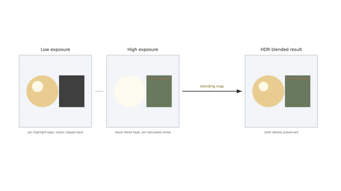
Set the exposure for the pins and resist print defects sink into darkness; set it for the resist and the pins saturate white, wiping out the scratches. A compromise value leaves both sides short of contrast, raising false alarms and misses together. Either way, defects on one material end up passing with no real inspection.
HDR1 multi-exposure fusion shoots the same scene several times at different exposures and merges them into one image, picking at each spot the value from the frame exposed well there. I judge this method by two questions: how many exposures are needed, and what that number demands in tact time and registration. The camera is assumed to be 2,448 × 2,048 px with 3.45 μm pixels, a full-well charge of 10,000 e⁻ and a read noise of 5 e⁻.
What a 249-to-1 brightness ratio leaves on the sensor
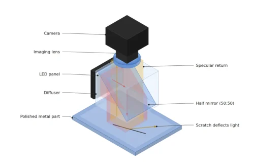
Under a coaxial light2, the brightness ratio of pin to resist is approximately specular reflectance × π ÷ (diffuse reflectance × source solid angle). Assuming a 10° source half-angle gives 0.60 × π ÷ (0.08 × 0.0947) = 249 to 1, or 8.0 stops of exposure. The sensor’s dynamic range3 is full-well charge ÷ read noise = 2,000 to 1, 66 dB or 11 stops, so on the numbers alone 249 to 1 fits with room to spare.
With the pins at 9,000 e⁻, 90 % of saturation, the resist receives 36 e⁻. Saturation is avoided and the resist is above zero, so one frame looks like enough, but finding defects is a different job from holding brightness. If a resist smear is 20 % darker than its surroundings, the signal difference is 7.2 e⁻, while photon shot noise4 and read noise together make each pixel wobble by 7.8 e⁻. The noise outweighs the signal.
Why one frame falls short even with ample dynamic range
Whether a defect shows is decided by the contrast-to-noise ratio, CNR5. Dividing the signal difference between defect and surroundings by the combined noise of two pixels, a 20 % contrast at 36 e⁻ of resist gives a CNR of 0.65. My criterion is a CNR of 3 or more, which requires the resist to receive 474 e⁻, so the exposure has to grow 13.1 times, or 3.7 stops. In a second frame exposed 16 times longer (4 stops), the resist receives 579 e⁻ and the CNR becomes 3.3.
The dB figure of dynamic range says only whether brightness fits between saturation and the noise floor; it says nothing about whether a defect on the dark side rises above the noise. These are different questions. The number of exposures is set by defect contrast in the dark region more than by the brightness ratio. For a weak defect with 10 % contrast, 1,825 e⁻ are needed, so the exposure must grow 50 times, or 5.7 stops, and a second frame at 64 times is the right fit. On the short-exposure side, the pins at 9,000 e⁻ give a CNR of 13.4 for 20 % contrast, which is plenty.
0.65CNR
Contrast-to-noise ratio of a resist defect (20 % contrast) in a single frame
16×
Second-exposure multiple that lifts the resist defect above CNR 3
26.7ms
Time for two exposures at 75 fps
Rules for merging two exposures
Merging for inspection serves a different purpose from merging for a good-looking photo. Linearity is the yardstick. My default is a linear merge that converts both frames back to light intensity before combining them. If a pixel in the long exposure is below 90 % of saturation, its value is used; above that, the short-exposure value multiplied by 16 is used, and the result is stored as a 16-bit linear image. This way, surfaces of the same reflectance carry the same value whichever frame they came from, so one threshold can judge them. The larger the multiple, the shorter the short exposure runs on signal in mid-brightness areas that just saturate in the long exposure, so if a 20 % contrast defect can also appear there, the multiple between the two exposures stays below 21 (10,000 e⁻ full well ÷ 474 e⁻ needed).
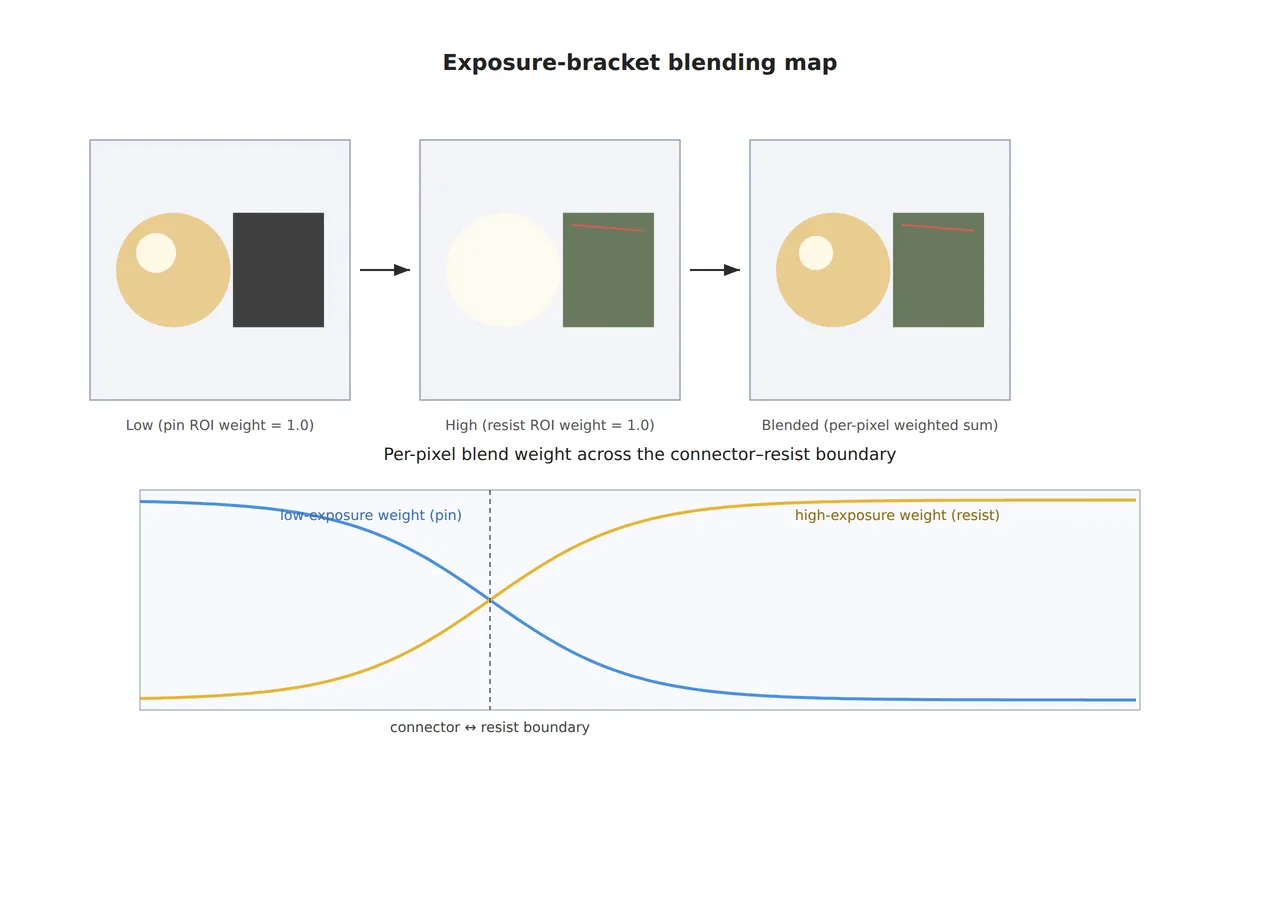
The blending map6 in the figure shows how deciding, pixel by pixel, which exposure frame to use reduces ghost artifacts7. US11107205B2 from Samsung Electronics, granted on August 31, 2021, covers generating blending maps with a convolutional neural network that reflect both motion between frames and how well each region is exposed, reducing ghosting. US12567188B2 from Keyence, granted on March 3, 2026, builds a separate conversion condition for each workpiece image that maps two input gradation values to the minimum and maximum of the output range. When a method whose conversion changes from image to image is paired with a fixed threshold, recording the conversion condition together with each image is the safer course.
The 13.3 ms between two frames
Shooting two separate frames opens a gap of one frame period. With a 75 fps camera, a 0.2 ms short exposure and a 3.2 ms long exposure (16 times) both fit inside the 13.3 ms frame period, and two frames take 26.7 ms. Motion is the problem. If the part moves even 10 mm per second in that time, it shifts 133 μm, or 16.7 pixels, so the same spot in the two frames records different points. Registration can line them up, but my default is the condition of shooting both frames with the part stopped, and the mechanical conditions for moving parts need a separate review.
Splitting and stacking exposures inside the sensor shortens this gap. On March 19, 2026, Vadzo Imaging announced the Innova-678CRS based on the Sony STARVIS 2 IMX678, stating up to 120 dB or more of dynamic range in Clear HDR and DOL-HDR modes, with 8.4 MP (3,856 × 2,180) resolution at 30 fps and GigE with PoE. In-sensor HDR keeps the time between exposures short, but whether its output is linear or compressed, and the frame rate in HDR mode, have to be confirmed from the manufacturer’s specs.
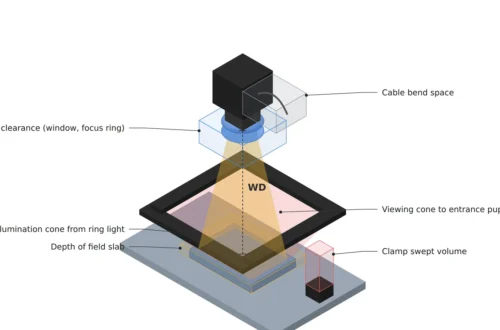
Here is the two-frame setup in one table. With the object pixel set at 8 μm, the field of view is 19.6 × 16.4 mm, and making a 0.431 magnification with a 25 mm lens puts the WD at about 83 mm by thin-lens approximation.
| Inspection item | ① Minimum defect size | ② Optical setup · WD | ③ Algorithm parameters · in plain words |
|---|---|---|---|
| Smear in matte resist print (20 % contrast) | 25 μm = 3.1 pixels (8 μm on the object) | 5 MP with 3.45 μm pixels, magnification 0.431, 25 mm lens, WD about 83 mm (thin-lens approximation), field of view 19.6 × 16.4 mm, coaxial light | Long exposure = short exposure × 16 (4 stops): resist at 579 e⁻, CNR 3.3 (0.65 in a single frame) |
| Scratches on nickel-plated pins | 25 μm | Same setup, pin highlights at 9,000 e⁻ (90 % of saturation) in the short exposure | Judged in the short-exposure frame, CNR 13.4 (20 % contrast) |
| Merge and tact | No size criterion | Two frames in 26.7 ms at 75 fps, part stopped during capture | Linear merge: long exposure below 90 % of saturation, otherwise short exposure × 16, stored as 16-bit linear, multiple between exposures under 21 |
Reading the three rows together, the number of exposures is set by the 16 times needed for a resist defect to clear CNR 3 on the dark side, and the 249-to-1 brightness ratio does not decide it; the price is the 13.3 ms between frames and the stopped-part condition. If defect contrast is a weak 10 %, the multiple grows to 64, and then the 21-times rule for mid-brightness areas decides whether a third exposure is needed.
When a dome or polarization does better
With a dome light8, whose source covers the whole hemisphere, the brightness ratio shrinks to specular reflectance ÷ diffuse reflectance = 7.5 to 1, so one frame can hold both materials. A dome, however, also erases scratches on glossy surfaces, which makes it hard to use when pin scratches are on the inspection list. If only the pin highlights are the problem and the defects on the pins are the kind that scramble polarization, cross-polarization finishes in one frame at the cost of 2.5 stops of light (85 % polarizer transmission assumed). In my judgment, on a line where moving parts make two frames hard to align, that option may be simpler than HDR. Which method wins depends on the gloss of the plating, the type of defect and the line conditions, so it cannot be guaranteed before a sample test.
HDR solves the problem with camera settings and software, leaving lighting and lens unchanged, so its upfront cost looks small. Yet the time for two frames, the registration processing and the stopped-part condition all add to the tact, so a fair comparison writes the cycle-time increase into the quote. This article explains technology and is not investment advice. See our Disclaimer.
Field Note
With nickel-plated pins and matte resist in one image, I would measure the brightness of both materials and the contrast of resist defects before deciding the number of exposures. In the exposure that puts the pins at 90 % of saturation, I measure the mean charge of the resist and the defect contrast, calculate the signal a CNR of 3 requires, and set the second-exposure multiple from it. If the multiple exceeds 21, I consider a third exposure for the mid-brightness areas. Then I measure the registration error between the two frames with the part stopped and with it moving, and if the moving error exceeds one pixel, I write still capture into the conditions.
Field Checkpoints
Once brightness measurements of both materials and the registration-error log have confirmed the assumptions behind the calculations, the remaining questions are these.
- Does the coaxial light fit within the WD of about 83 mm (25 mm lens, thin-lens approximation)?
- Have you measured the CNR of resist defects in the exposure that puts the pins at 90 % of saturation? (Calculated: 0.65)
- Is the second-exposure multiple high enough to clear CNR 3 (16 times for 20 % contrast), and is the multiple between the two exposures below 21?
- Does the part stay still for the 26.7 ms it takes to shoot two frames?
- Is the merged result linear, and if it is in-sensor HDR, have you confirmed the output format from the datasheet?
- Have you set the decision threshold for the merged image with resist and pin defect samples?
Frequently Asked Questions
Are three or more exposures better?
More exposures cut noise in mid-brightness areas, but each one adds a 13.3 ms frame period and more registration work. In a scene where the two materials separate cleanly, two frames are often enough, and where defects can also appear in mid-brightness areas, such as the curved sides of the pins, three frames are worth reviewing so that adjacent exposures stay under a 21-times multiple.
Does the same calculation hold for a color camera?
In a color sensor, each pixel’s color filter passes only part of the light, so charge falls at the same exposure and the calculation has to be redone per channel. Nickel plating is nearly colorless, but green resist reflects differently in each channel, so the exposure multiple is best set from the channel with the largest defect contrast.
Glossary
- [1] HDR HDR
Techniques for holding bright and dark areas in one image. The text covers merging two frames taken at different exposures. ↩ - [2] Coaxial light on-axis light
Lighting sent along the lens axis through a half mirror. Flat metal surfaces look very bright. ↩ - [3] Dynamic range DR
The ratio of the brightest to the darkest signal a sensor can hold in one frame, calculated as full-well charge ÷ read noise. ↩ - [4] Shot noise photon noise
Fluctuation caused by photons arriving at random. It equals the square root of the signal. ↩ - [5] CNR CNR
The signal difference between a defect and its surroundings divided by noise. The text uses 3 or more as its criterion. ↩ - [6] Blending map weight map
A weight map recording, for each pixel, how much of each frame’s value goes into the merge. ↩ - [7] Ghost artifact ghosting
A doubled trace in a merged image caused by the object moving between shots. ↩ - [8] Dome light cloudy-day light
Lighting in which a hemispherical diffuser sends light evenly from every direction. It suppresses both highlights and scratches on glossy surfaces. ↩
References
- Vadzo Imaging, Vadzo Imaging Launches Innova-678CRS: 4K HDR GigE Vision Camera Powered by Sony STARVIS 2 IMX678 (2026-03-19, Clear HDR and DOL-HDR, up to 120+ dB, 8.4 MP at 30 fps)
- Samsung Electronics, US11107205B2, Techniques for convolutional neural network-based multi-exposure fusion of multiple image frames and for deblurring multiple image frames (granted 2021-08-31, blending maps reflecting motion and exposure)
- Keyence, US12567188B2, Image processing apparatus (granted 2026-03-03, gradation conversion condition generated per workpiece image)
- refractiveindex.info, Optical constants of Ni (Johnson and Christy 1974) (n = 1.92 and k = 3.61 at 0.549 μm, normal reflectance 64 %)
- Formulas: brightness ratio = specular reflectance × π ÷ (diffuse reflectance × π sin²(half-angle)), dynamic range = full-well charge ÷ read noise, CNR = contrast × signal ÷ √(2 × (signal + read noise²)), required exposure multiple = signal needed for CNR 3 ÷ single-frame signal, adjacent-exposure multiple limit = full-well charge ÷ needed signal, inter-frame shift = speed × frame period, WD ≈ f × (1 + 1/m)
Related reading — How Strongly Cross-Polarization Suppresses Glare Depends on the Lighting Angle · For Scratches on Highly Reflective Metal, Choose the Lighting First · The Cost of Switching Between Dark-Field and Coaxial with Software-Defined Lighting

Noctvision
An engineer who has handled mechanical design and project management for production equipment since 2005. Here I work through the cameras, lenses and lighting that go into equipment with formulas and public data, and record the assumptions and sources alongside the numbers.


You May Also Like
Vision Types Split First by Wavelength and Pixel Size
Coaxial Light Alone Does Not Settle Fine Scratches on Polished Metal