For Scratches on Highly Reflective Metal, Choose the Lighting First
LIGHTING
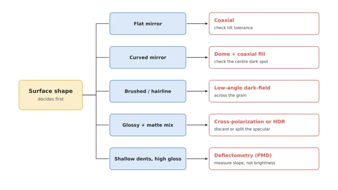
Lighting for scratches on polished or plated metal is first split by surface shape, and coaxial light without a diffuser on a flat mirror finish darkens the background once the tilt passes 0.93°.
Pairing four surfaces (flat mirror, curved mirror, hairline, mixed gloss and matte) with coaxial, dome, low-angle, cross-polarized and HDR lighting, I calculated tilt tolerance, light budget and the brightness range one frame can hold.
About 12 min read
Scratch inspection of polished metal or plated parts usually starts from the same screen. Part of the frame saturates to white, and the scratch that should be inside that highlight cannot be seen. Lower the exposure and everything else goes dark; change the threshold and the reflection boundary gets caught as a defect.
Hold out at this stage with filters and thresholds, and overdetection and missed detection grow by turns. Defect information inside saturated pixels1 cannot be recovered by any postprocessing, so time spent polishing the algorithm with the wrong lighting method piles up directly as escape risk. Change the filter three times on the same screen, and the white area stays white.
So I split the lighting first by two questions: the shape of the surface and the shape of the scratch. Whether the surface is a flat mirror, a convex mirror, a hairline finish with machining lines running one way, or a mix of gloss and matte changes the first candidate. The calculations use one setup throughout: a 4,096 × 3,000 px camera with 3.45 μm pixels and a 75 mm F5.6 lens. Setting 6.0 μm/px to see a 20 μm wide scratch over 3.3 pixels gives a FOV of 24.6 × 18.0 mm and about 205 mm from the lens principal plane to the part.
A flat mirror finish starts with coaxial, tolerance first
For scratches on a flat polished surface or a mirror-finish cover, coaxial illumination2 is the first candidate. Light coming down the optical axis returns from the flat mirror into the lens and makes a bright background, while the tilted walls of a scratch throw the light out of the lens and remain as a dark line. The brighter the background, the sharper the dark line, so this method lives or dies by how evenly bright the background is.
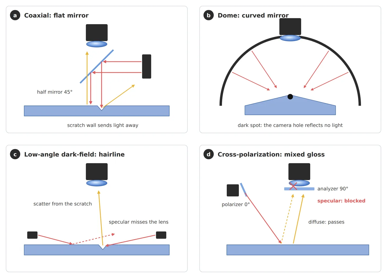
In panel (a), compare the two yellow arrows. Light rising straight from the flat surface enters the lens, and light glancing off the groove wall misses it. The catch is that if the surface that should be flat tilts even slightly, the background light misses the lens too. When the surface tilts by α, the reflected light turns by 2α, so the tilt tolerance3 within which the background stays bright is (lens aperture half-angle + light spread) ÷ 2.
The aperture diameter of a 75 mm F5.6 lens is 75 ÷ 5.6 = 13.4 mm, and seen from the part 205 mm away, the aperture half-angle is 1.87°. Coaxial light without a diffuser has zero spread, so its tolerance is 0.93°, and diffuse coaxial with an assumed spread of ±10° gives 5.93°. If fixture tilt and polishing waviness stay within 0.93°, coaxial without a diffuser shows even the shallowest scratch as dark; beyond that, diffuse coaxial keeps the background but renders gentle grooves as bright as the background.
0.93°
Tilt tolerance of coaxial light without a diffuser (aperture half-angle 1.87°)
5.93°
Tolerance of diffuse coaxial with an assumed ±10° spread
25%
Maximum share of light returning after passing a 50:50 half mirror twice
The third card is the light budget. A 50:50 half mirror4 reflects half of the light going down and passes only half of the light coming back, so the light returning to the sensor is at most 25% of the source output. When choosing coaxial, I would measure the fixture tilt about ten times and only then pick the source output. The full tolerance calculation is in the coaxial lighting article.
Curved mirror finishes take a dome; count where the hole reflects
A part that is both curved and mirror-like, such as a convex plated cap, has a different tilt at every spot and does not fit inside the coaxial tolerance. The default here is dome illumination5. It turns the whole inside of a hemisphere into a light source, so whichever way the curve tilts, it reflects a glowing wall.
The price is the camera hole at the top. The hole gives off no light, so the spot that reflects it stays dark (panel (b)). If there is a flat mirror zone, the calculation is simple. With the camera looking down from the height of the hole, a point on the surface reflects the point at dome height twice as far out horizontally, so a circle half the diameter of the hole comes out black. With a 20 mm hole, the dark spot on a flat zone is 10 mm across. On a convex curve it gets smaller, with a size that depends on the curvature, so that calculation follows the dome dark-spot article.
When I use a dome, I calculate the effective inspection area before the resolution. Masking the dark spot leaves that area uninspected for good, so I choose to add coaxial fill light inside the dome to fill the hole’s spot. The dome also has to be large enough to cover the part, so the WD6 and dome diameter must be matched together.
Hairlines are crossed with low light
For a hairline surface with machining lines running one way, or for shallow scratches, low-angle dark-field lighting7 can work better. Light coming in at a low angle reflects specularly8 off the flat surface and misses the lens, and only light turned by the sloped walls of a flaw enters the lens, making a bright line on a dark background (panel (c)). On a surface where the machining lines themselves are sloped, the coaxial background fills with stripes, so the difference grows larger.
For light coming in 15° above horizontal to turn toward the lens, the surface has to tilt by about (90° − 15°) ÷ 2 = 37.5°. Adding this setup’s half field angle of 3.42° and aperture half-angle of 1.87° to the calculation narrows the tilt of glowing walls to about 35 to 40°. The flat background falls outside this range and stays dark, and only flaws with steep walls rise as lines. To my eye, this narrow range of angles is both the strength and the weakness of low-angle lighting.
What matters is aiming the light perpendicular to the machining lines. Light arriving parallel to the lines barely catches their walls. For parts with defects in several directions, split the captures by direction with quadrant lighting or multichannel lighting. A setup combining dark-field with decision logic trained only on defect-free samples is in the dark-field illumination article, and one that switches between dark-field and coaxial on a single head is in the software-defined lighting article.
Mixed gloss and matte: discard or split
When plated pins and a matte molded housing share one frame, either discard the specular reflection with cross-polarization or split the two materials across frames with HDR multi-exposure9. Cross-polarization10 sets the polarizer on the light and the analyzer on the lens at 90° to block specular reflection that keeps its polarization (panel (d)), and HDR merges several frames with different exposures to hold a brightness gap one frame cannot.
In numbers, the price of each method is clear. Even with ideal polarizers, half is lost at the source, and diffuse reflection11, its polarization scrambled, loses half again through the analyzer, so the light from the matte housing falls to around 25% of what it would be without polarizers. The brightness range one 12-bit frame holds is 4,096 levels, 72.2 dB in theory, and if the plated pin’s highlight is 10,000 times (80 dB) brighter than the housing, it does not fit in one frame. Shooting two frames with exposures 16 times apart and merging them widens the range that can be held by 24.1 dB.
The deciding question is whether the information inside the specular reflection is needed. If not, choose cross-polarization; if so, choose HDR. On a line that must also find scratches on the pins, I would raise my hand for HDR first. If cross-polarization is chosen, factor in that metal specular reflection can carry circularly polarized components, so its blocking wavers with material and angle of incidence (cross-polarization article). HDR needs the part to stay still while the frames are taken, or the images to be registered precisely (HDR multi-exposure article). When the shape itself is the defect, as with shallow sink marks on high-gloss molding, measuring the slope directly can be the right method instead of either (phase measuring deflectometry (PMD) article).
Four lines chosen by surface shape
Moved into spec-sheet lines, the four surfaces read as below. The lighting column is the method to try first, and the basis column records the limit that method holds up to.
| Item | Value | Condition · basis | In plain words |
|---|---|---|---|
| ① Minimum defect size | 20 μm wide scratch = 3.3 px (6.0 μm/px) | 4,096 × 3,000 px, 3.45 μm, 75 mm F5.6, FOV 24.6 × 18.0 mm | A little over three pixels across the scratch |
| ② Flat mirror | Coaxial without a diffuser (fixture tilt within 0.93°), diffuse coaxial (5.93°) beyond | Tolerance = (aperture half-angle 1.87° + spread) ÷ 2, at most 25% of the light through the half mirror | A 0.93° tilt is enough to darken the background |
| ② Curved mirror | Dome + coaxial fill light | Dark spot on a flat zone = half the hole diameter (10 mm for a 20 mm hole), smaller on curves | Fill the spot where the camera hole reflects |
| ② Hairline | 15° low-angle light perpendicular to the machining lines | Glowing wall tilt about 35 to 40° (half field angle 3.42°, aperture half-angle 1.87°) | Cross the lines with low light |
| ② Gloss + matte | Cross-polarization (about 25% of the light) or two HDR frames (16× exposure, +24.1 dB) | One 12-bit frame 72.2 dB; a 10,000× brightness ratio is 80 dB | Discard the reflection or split it across two frames |
| ② WD | About 205 mm from the lens principal plane to the part, real WD fixed with the lens data | Coaxial housing height, dome diameter and low-angle ring height all inside the WD | Each light takes a different height |
| ③ Algorithm parameters | Count saturated pixels separately as not inspectable; filters only after lighting and exposure have reduced saturation | Defect information in saturated areas does not come back (filtering order article) | A blown-out area is an uninspected area |
The first criterion that splits the lighting choice is surface shape, ahead of defect size. Even for the same 20 μm scratch, when the surface changes to hairline the first candidate moves from coaxial to low-angle light, and on a curved surface it moves to a dome. Each method takes a different height within the WD, so if two or more candidates remain, it is safer to reserve space for both at the layout stage.
Sometimes another method fits better. Diffuse-finished metal such as bead-blasted parts reflects too weakly to form coaxial’s bright background, so oblique lighting does better on both light quantity and contrast. If the defect is color or discoloration more than shape, wavelength selection may fit better than lighting angle (wavelength selection article). If one-directional lighting already gives enough contrast, methods that spend more space and capture time, such as a dome or HDR, are overkill. The reflectance of metal surfaces changes a great deal with polishing conditions, coatings and oxide layers, so which lighting will win cannot be guaranteed before a sample test.
Choosing lighting from surface shape is a judgment worth having in hand before opening a catalog, for anyone new to lighting. From the side that sets the equipment budget, reserving space for both methods when two candidates remain costs less than remaking the fixture when the lighting changes later. This article explains technology and is not investment advice. See our Disclaimer.
Field Note
When a highly reflective metal part arrives, I would split the surface four ways and write a lighting candidate for each area before any talk of filters. For the flat mirror zone, I seat the part in the fixture ten times to see whether the coaxial background holds within the 0.93° tolerance, and for the curved zone, I measure the size of the spot where the dome hole reflects. If the lighting has to be split across two captures, inspection time must be divided again, so the per-area lighting table and capture times go in the same table. The height each light takes within the WD is one more cell in that table.
Field Checkpoints
Before moving the field note’s per-area table into a lighting spec, answer the questions below.
- Is the height each candidate light takes secured together with the WD? (including coaxial housing height, dome diameter and low-angle ring height)
- Has the surface first been split into flat mirror, curved mirror, hairline and mixed? (the first candidate changes even for the same scratch)
- For coaxial, do fixture tilt and polishing waviness stay within the tolerance? (0.93° without a diffuser, 5.93° with ±10° spread)
- For a dome, have the size of the dark spot where the hole reflects and the effective inspection area been calculated? (half the hole diameter on a flat zone)
- Has saturation been reduced with lighting and exposure before filters touch it? (saturated pixels are counted separately as not inspectable)
- Have comparison captures been taken per method with boundary samples? (reflectance varies with lot and coating)
Frequently Asked Questions
Can a single polarizing filter erase metal reflections?
Metals twist the polarization state when reflecting at an angle, so they are often not blocked as cleanly as non-metal surfaces. Spots where blocking falls short can still saturate, so even with cross-polarization, count saturated pixels separately to confirm the effect.
With HDR, how many exposures are needed?
It is set by the brightness ratio to be held and the range of one sensor frame. If the ratio is 80 dB and one frame holds 72.2 dB in theory, two frames are enough on paper, but a real sensor’s range is narrower than the theoretical value because of noise, so the exposure ratio is set with margin. More frames also mean more time the part has to stay still.
Why not choose the filter first?
Saturated pixels hold no defect information, so the filter has nothing to work on. The right order is to reduce saturation with lighting and exposure, then choose an edge-preserving filter such as a bilateral filter, and the calculation behind that order is in the filtering order article.
Glossary
- [1] Saturation saturation
The state in which a pixel has reached the brightest value it can hold and can no longer tell brighter light apart. A blown-out white area keeps no trace of defects either. ↩ - [2] Coaxial illumination coaxial illumination
Lighting sent down along the camera optical axis by a half mirror. Flat glossy areas look bright and tilted slopes look dark. ↩ - [3] Tilt tolerance tilt tolerance
The largest angle a surface that should be flat can tilt while the background stays bright. Reflection turns by twice the tilt, so it is smaller than expected. ↩ - [4] Half mirror beam splitter
A mirror that reflects half the light and passes the other half. Light passes it twice on the way down and back, so a quarter returns. ↩ - [5] Dome illumination dome illumination
Lighting in which the whole inner wall of a hemisphere glows evenly and wraps the part from every side. The camera looks in through a hole at the top. ↩ - [6] WD working distance
The distance from the front of the lens to the surface being inspected. Coaxial housings, domes and low-angle rings all have to fit inside it. ↩ - [7] Low-angle dark-field lighting dark-field
Lighting from a low angle so that the reflection from a flat surface misses the lens. The background stays dark and only the walls of flaws glow. ↩ - [8] Specular reflection specular reflection
Reflection in which light bounces off a smooth surface in one direction only, at the same angle it came in. A flashlight seen in a mirror is an example. ↩ - [9] HDR multi-exposure HDR
Merging several frames taken at different exposures to hold a wider brightness range than one frame. If the part moves during capture, the merged image misaligns. ↩ - [10] Cross-polarization cross-polarization
Blocking specular reflection by crossing the polarizer on the light and the analyzer on the lens at 90°. Diffuse reflection has scrambled polarization, so part of it passes. ↩ - [11] Diffuse reflection diffuse reflection
Reflection in which light scatters back in every direction from a rough surface or a pigment layer. It looks about equally bright from any direction. ↩
References
- Edmund Optics, System Throughput, f/#, and Numerical Aperture: f/# = focal length ÷ effective aperture diameter
- Formulas: coaxial tolerance = (aperture half-angle + light spread) ÷ 2, aperture half-angle = arctan(f ÷ N ÷ 2 ÷ object distance), tilt of facets that glow under low-angle light = (90° − elevation ∓ (half field angle + aperture half-angle)) ÷ 2, dome dark-spot diameter on a flat mirror = hole diameter ÷ 2, dynamic range = 20 × log10(brightness ratio). Assumptions: 4,096 × 3,000 px, 3.45 μm, 75 mm F5.6, 6.0 μm/px, object distance about 205 mm, diffuse coaxial spread ±10°, ideal polarizers
Related reading — How to Handle Imaging on Highly Reflective Surfaces · Six Machine-Vision Lighting Methods and How to Choose · Coaxial Light Alone Does Not Settle Fine Scratches on Polished Metal

Noctvision
An engineer who has handled mechanical design and project management for production equipment since 2005. Here I work through the cameras, lenses and lighting that go into equipment with formulas and public data, and record the assumptions and sources alongside the numbers.


You May Also Like
A Dark-Field Ring Light Tolerates Far More Tilt Than Coaxial Light
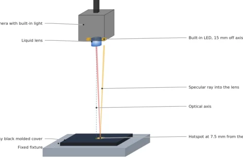
Raising the Camera Leaves the Glint of Its Built-in Light in Place