Reserve Room for Vision Cameras and Lighting at the Mechanical Design Stage
OPTICS
Calculated from the diagonal and mounting height, a ring light’s opening needs 106.5 mm, and a low-angle ring claims a band 10.7 mm above the part before anything else.
Using a connector inspection station as the example, I followed the calculation that reserves the viewing cone, illumination cone, depth of field and service clearance as transparent volumes in 3D CAD first.
About 12 min read
Try to fit a vision station into the space left over after the mechanical design of the equipment is finished, and the camera fits while the light does not. A low-angle ring light has to come down close to the part, a dome light needs a diameter far larger than the part, and a coaxial light housing takes up height in front of the lens. A camera bracket can be squeezed in later somehow, but when a light has no room, its whole method changes.
Shorten the WD1 for lack of space, and magnification, FOV and resolution change one after another. Change the lens, and the light position goes off again, until the bracket, fixture and cover have to be remade or the lighting method compromised. Compromised lighting loses contrast, and contrast that never made it into the image cannot be fully restored by an algorithm.
So I design a vision station as a space before designing it as parts. The example station inspects a connector with metal pins set in a matte molded housing. The housing scatters light in every direction and the pins throw it back in one direction, so assume a ring light on the camera that views the whole housing and a low-angle ring light on the camera that views the pin-tip area. Put the space both lights will occupy into 3D CAD first as transparent volumes, and the mechanical parts are drawn around those volumes from the start.
Four volumes the light passes through
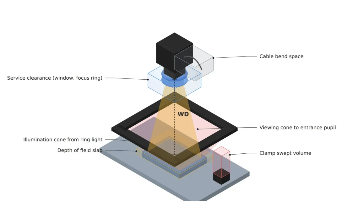
The space a vision station occupies is set by the volumes the light passes through more than by the outline of the camera and lens. They are the viewing cone3 running from the part’s FOV to the lens entrance pupil2, the illumination cone through which light comes from the source to the part, the depth of field4 slab that holds the part’s height variation, and the service clearance needed to wipe the protective window, turn the focus ring and bend the cable. If even one of the four is blocked by hardware, it shows up on screen as vignetting5, a shadow or lost focus.
Take the clamp lever that holds the connector in the fixture: in the static assembly drawing it shows no interference with the illumination cone. But if the moment the lever passes into the illumination cone on its way overlaps with a capture, a shadow falls on that edge only, and overdetection follows. So a moving part has to be turned into one volume covering its whole path, a swept body6, and checked against the keep-out space. I would ask for the lever’s path to be drawn before accepting any static drawing.
With the four volumes built as transparent bodies in CAD, the mechanical designer can protect vision performance with interference checks alone, without any optical calculation. The rule shrinks to one line. Do not touch the transparent volumes. What remains is to set the size of those volumes in numbers. The first number is the ring light’s opening.
Ring light openings are measured on the diagonal
A light placed between lens and part, such as a ring light or a coaxial housing, needs an opening wider than the viewing cone at that height. With a regular lens, the rays from the edge of the FOV converge toward the lens entrance pupil, so the opening needed at height h above the part is W(h) = FOV × (1 − h/u) + D × h/u. Here u is the object distance to the entrance pupil and D is the entrance pupil diameter, and for a round opening the diagonal has to go in instead of the horizontal FOV width to keep all four corners.
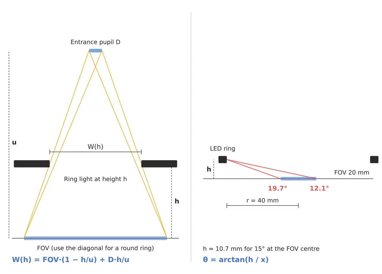
The two pairs of yellow lines on the left of the figure are rays converging from both ends of the FOV to the entrance pupil, and the distance between the two outer lines at the ring height is W(h). Take the housing camera’s FOV as 100 × 73.2 mm at the 4,096 × 3,000 px aspect ratio, the object distance as 202 mm, and approximate the entrance pupil of a 25 mm F4 lens as 25 ÷ 4 = 6.25 mm. Put in the 123.95 mm diagonal, and W at 30 mm above the part is 106.5 mm. Choosing a ring with a 100 mm inner diameter by looking only at the 100 mm width can cover the four corners.
Change the height, and the numbers move the opposite way. Lower the ring to 10 mm above the part, and the opening needed widens to 118.1 mm; raise it to 50 mm, and it narrows to 94.8 mm. The viewing cone grows thinner toward the lens. With an object-side telecentric lens7, the chief rays are parallel and the width does not shrink with height, so the opening has to be larger than the FOV. The real position and diameter of the entrance pupil vary by lens design, so I use this calculation to choose candidates and fix the final value with the lens data. How to find u and D is in the lens calculator article.
A low-angle ring occupies a band 10.7 mm high
With low-angle lighting8, the desired angle of incidence sets the mounting height of the light, so it has to claim its place first in the mechanical design. If the ring source sits at height h above the top of the part and the horizontal distance between a point on the source and the point on the part where the light lands is x, the elevation angle9 measured from the horizontal is θ = arctan(h ÷ x). Since x is not a single value across the FOV, the elevation angle becomes a range instead of one value.
Light the pin-tip area (20 mm FOV) with a 40 mm radius ring and set the central elevation to 15°, and h = 40 × tan 15° = 10.7 mm. From the same source, the near end of the FOV (x = 30 mm) receives light at 19.7° and the far end (x = 50 mm) at 12.1°, a spread of 7.6°. To my eye, this spread is the weak point of the setup. The same defect can light up at a different brightness depending on where it sits in the FOV. Enlarge the radius to 60 mm, and the spread shrinks to 4.9°, but the ring takes a wider annulus and its height rises to 16.1 mm. The lower the elevation, the further the source comes down toward the part, where it runs into the fixture and clamps first. The calculation for cases that truly need a low angle, such as molded characters, is in a separate article on low-angle ring light and molded characters.
106.5mm
Opening needed for a ring light 30 mm above the part (on the FOV diagonal)
10.7mm
Mounting height of a 40 mm radius ring at a 15° central elevation
5.4mm
Height a clamp at a 25 mm radius must not exceed
The third card is the most direct number for the mechanical designer. If a clamp jaw comes in between the ring and the FOV, it has to pass below the light running from the ring to the near end of the FOV to avoid casting a shadow. At a 25 mm radius, the limit is 10.7 × (25 − 10) ÷ (40 − 10) = 5.4 mm, and at a 35 mm radius it is 8.9 mm. By my rule, this wedge-shaped volume is the real keep-out space of low-angle lighting.
Transparent volumes go into CAD first
The keep-out space is built as a layout model early in the mechanical design, and every mechanical part references that model. Assemble the camera and light models later, and interference can be checked but space cannot be reserved. Put the volumes in first, and the fixture, cover and wiring designs avoid that space from the beginning. By my rule, this model should exist before the kickoff meeting.
Five steps are enough. First, add the height variation to the FOV rectangle on top of the part to make a slab as thick as the depth of field, and loft from the four FOV corners to the entrance pupil circle to make the viewing cone. Next, build the illumination cone from the source position to the FOV; for a low-angle ring it becomes an annular wedge. Then reserve room to remove the protective window and cap in front of the lens and the space where the cable bends behind the camera, using the minimum bend radius from the cable datasheet. Finally, turn the motion paths of the fixture and clamps into swept bodies and run interference checks against the four volumes.
Applied to the example, the housing camera’s viewing cone passes through a 106.5 mm diagonal section at 30 mm above the part, and the pin camera’s low-angle ring occupies an annulus of 40 mm radius at a height of 10.7 mm above the top of the part. The depth-of-field slab is about 3.15 mm thick for a 4,096 px sensor at F4 with a two-pixel circle of confusion, so the part height variation plus the fixture seating error has to fit inside it. When the lens or light changes, redrawing only the volumes shows the extent of the impact at once.
Reserving space in three spec lines
Moved into a spec sheet, the sizes of the transparent volumes read as below. The basis is the condition of seeing a 100 μm defect with the housing camera, and the pin camera’s low-angle ring is listed in the optical lines as well.
| Item | Value | Condition · basis | In plain words |
|---|---|---|---|
| ① Minimum defect size | 100 μm (housing), about 4.1 px at 24.4 μm/px | Design assumption. 100 mm FOV on 4,096 px | One defect covers a little over four pixels |
| ② Lens · WD | 25 mm F4, object distance u about 202 mm, entrance pupil about 6.25 mm | Real WD, lens front to top of part, fixed with the maker’s data and including light height, coaxial housing and protective window thickness | Leave room for the light between lens and part |
| ② Ring light opening | Inner diameter of at least 106.5 mm at h = 30 mm | FOV diagonal 123.95 × (1 − 30/202) + 6.25 × 30/202 | Choose by width alone and the corners get cut |
| ② Low-angle ring (pin area, 20 mm FOV) | Radius 40 mm, height about 10.7 mm, elevation 12.1 to 19.7° | θ = arctan(h ÷ x). A clamp at a 25 mm radius stays at 5.4 mm or lower | Keep the low band between ring and part clear |
| ② Depth-of-field slab | About 3.15 mm (c of two pixels) | Part height variation + fixture seating error inside it | The thickness that stays in focus |
| ③ Algorithm parameters | Monitor the mean brightness of four corner ROIs on good-part images | Early sign of a keep-out intrusion. Alarm threshold set from measurement | If a corner darkens, something is blocking the light |
| ③ Shadow handling | Never cover a shadow caused by intrusion with a mask | A masked area stays uninspected | A covered area is an uninspected area |
The first thing the table shows is that lighting space is not set by catalog dimensions. Compared with the 100 mm FOV width, the ring opening looks roomy, but with the diagonal and mounting height it needs 106.5 mm, and the low-angle ring spreads its elevation by 7.6° even within a narrow band 10.7 mm high. Both numbers come only from a calculation that includes the FOV, the height and the entrance pupil. Choosing by catalog inner diameter alone is too late.
Sometimes another approach fits better. For a simple inspection of a small part under a single standard light, the lighting supplier’s standard brackets and distance tables may be enough without keep-out modeling. A module in which coaxial light and a telecentric lens form one body keeps its optical space closed inside the module outline, so only the outline and WD need managing. On a retrofit whose layout is already fixed, space cannot be created by calculation, so folding the optical path with a mirror is worth reviewing, though the mirror’s reflectance and contamination control come along as new variables. Even with the light position settled, how much contrast the defects will show against the gloss of the metal pins cannot be guaranteed before a sample test.
Optical keep-out space translates optics into the most familiar language for anyone moving from mechanical design into vision: interference checking in 3D CAD is already a tool in hand. From the side that orders the equipment, simply asking for these volumes at the kickoff meeting cuts the cost of re-machining brackets. This article explains technology and is not investment advice. See our Disclaimer.
Field Note
Before a kickoff meeting, I would bring two numbers first: the 5.4 mm height a clamp at a 25 mm radius must not exceed, and the sum of the ring light and protective window thicknesses that has to fit inside the WD measured from the lens front. If the low-angle ring’s height band overlaps the clamp path, the lighting method has to change, and the pin-tip contrast can drop a notch. That is why I ask for the FOV rectangle and the illumination cones to go in as transparent bodies early in the design.
Field Checkpoints
Widened into drawing review items, the field note’s two numbers read as below.
- Is the WD from the lens front to the top of the part secured on the drawing with light height, coaxial housing and protective window thickness all included? (the light has to fit inside the WD)
- Is the ring light opening wider than the width calculated from the FOV diagonal, mounting height and entrance pupil? (106.5 mm at h 30 mm)
- Does the low-angle ring’s height band stay clear of the swept bodies of the fixture and clamps? (5.4 mm or lower at a 25 mm radius)
- Does the depth-of-field slab hold the part height variation and fixture seating error? (about 3.15 mm)
- Is there service clearance for removing the protective window, turning the focus ring and the cable bend radius? (using the cable datasheet values)
- Are the four corner brightness levels of good-part images monitored to catch keep-out intrusions? (shadows are never masked)
Frequently Asked Questions
Why is the entrance pupil diameter approximated as f ÷ N?
Because the f-number is the focal length divided by the effective aperture diameter, D comes straight from the lens markings. For a 25 mm F4 lens, it is 6.25 mm. How far inside the lens front the entrance pupil sits is not in the markings, though, so u is confirmed with the lens data.
What changes with a dome light?
A dome has to be large enough to cover the part and has a camera hole at the top, so the keep-out space becomes the whole hemisphere above the part. The paths by which clamps and parts come and go cannot enter under the dome, so the motion of raising and lowering the dome becomes part of the mechanical design. The dark spot the hole creates is calculated in the dome light dark-spot article.
How can the elevation range of a low-angle ring be narrowed?
Enlarging the radius reduces the ratio of distances to the two ends of the FOV, which narrows the range. At a 15° central elevation, a 40 mm radius gives 7.6° and 60 mm gives 4.9°. In exchange, the height rises from 10.7 mm to 16.1 mm, and the limit for a clamp at a 25 mm radius actually drops from 5.4 mm to 4.8 mm, so the clamp height has to be recalculated.
Glossary
- [1] WD working distance
The distance from the front of the lens to the surface being inspected. Ring lights, coaxial housings and protective windows all have to fit inside it. ↩ - [2] Entrance pupil entrance pupil
The image of the aperture stop seen when looking into the front of the lens. Rays from the object converge toward this circle. ↩ - [3] Viewing cone viewing cone
The cone-shaped volume formed by rays running from the four FOV corners to the entrance pupil. Anything entering it darkens the edges of the frame. ↩ - [4] Depth of field DOF
The range of depth that stays sharp in front of and behind the focus distance. In CAD it is drawn as a thin slab over the part. ↩ - [5] Vignetting vignetting
Darkening of the edges or corners of the frame because part of the rays is blocked. Light drains from the corners first, as in a photo taken through a window frame. ↩ - [6] Swept body swept body
A single solid representing the whole path a moving part travels. It catches interference that the static assembly drawing hides. ↩ - [7] Telecentric lens telecentric lens
A lens whose object-side chief rays run parallel to the optical axis, so magnification barely changes with distance. Its field becomes a column instead of a cone. ↩ - [8] Low-angle lighting low-angle lighting
Lighting that sends light at a low angle, almost lying across the top of the part. It leaves flat areas dark and makes only raised or recessed spots glow. ↩ - [9] Elevation angle elevation angle
The tilt of the light measured upward from the horizontal. Even from the same ring it differs between the near and far ends of the FOV. ↩
References
- Edmund Optics, System Throughput, f/#, and Numerical Aperture: f/# = focal length ÷ effective aperture diameter
- Formulas: W(h) = FOV × (1 − h/u) + D × h/u, D ≈ f ÷ N, θ = arctan(h ÷ x), clamp limit = h × (x − FOV/2) ÷ (r − FOV/2), DOF ≈ 2 × N × c × (1 + m) ÷ m². Assumptions: FOV 100 × 73.2 mm, u 202 mm, 25 mm F4, low-angle ring radius 40 mm with a 15° central elevation, pin-area FOV 20 mm
Related reading — The Black Spot in the Middle of a Dome Light Is the Camera Hole · One Lighting Angle Decides the OCR Read Rate on Molded Characters · Coaxial Light Alone Does Not Settle Fine Scratches on Polished Metal

Noctvision
An engineer who has handled mechanical design and project management for production equipment since 2005. Here I work through the cameras, lenses and lighting that go into equipment with formulas and public data, and record the assumptions and sources alongside the numbers.


You May Also Like
Raising the Camera Leaves the Glint of Its Built-in Light in Place
In SWIR Imaging, Lighting and Aperture Keep the Defect Contrast