When Specular and Matte Meet in One Frame: Reviving Contrast with HDR Multi-Exposure Fusion
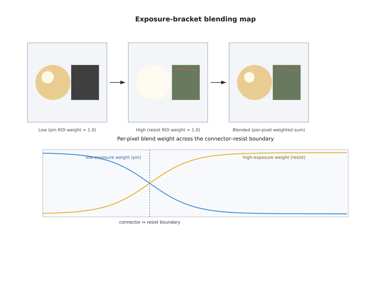
At an inspection station where a nickel-plated connector pin and a matte resist print surface both fall within the same camera field of view (FOV), setting exposure for the connector buries the resist printing defect in shadow and loses it, while setting exposure for the resist saturates the connector pin’s specular reflection to white and erases the scratch on top of it. No matter how the lighting angle or intensity is adjusted, once the reflectivity difference between the two materials exceeds a single camera sensor’s dynamic range, one exposure value cannot capture both at once.
Leaving this unaddressed hardens the inspection line into a structure that always sacrifices one of the two materials. With connector-based exposure, resist defects leak through as missed detections; with resist-based exposure, connector surface defects get buried in the saturated region and are likewise missed. Even splitting the difference on exposure often leaves both sides short on contrast, increasing both false and missed detections at once. This article organizes how HDR multi-exposure fusion, which goes beyond the limits of a single exposure, works on a surface where specular and matte regions are mixed, and when it is favorable or unfavorable compared to the cross-polarization method covered in an earlier article.
Why a single exposure can’t capture two materials at once
The native dynamic range of an industrial CMOS sensor is typically on the order of 60–70 dB, which means that once the brightness ratio between highlights and shadows exceeds roughly 1,000:1, one side gets clipped — lost to saturation or to the noise floor. The specular luminance of nickel plating or polished metal commonly appears tens to hundreds of times higher than the diffuse-reflection luminance of a matte resist print surface, and once that difference exceeds the sensor’s native range, whichever side the exposure is set for, the other side’s information is physically lost.
The problem is that this loss is not a geometric error like distortion. A saturated pixel has lost the brightness information of whatever defect was originally there, and it cannot be recovered through post-processing software filtering. Keyence’s 2026 patent (US12567188B2) approaches this problem by generating an individual gradation-conversion condition per workpiece image. The core idea is calculating, frame by frame, a different condition that maps a specific gray-level value of the input image to the minimum and maximum values of the output range, so that even as the target changes, an appropriate gradation range can be automatically re-set each time.
How HDR multi-exposure fusion works
HDR multi-exposure fusion captures several images of the same scene at different exposure values, then composites a single image by selecting only the best-exposed information from each region across the frames. In a low-exposure frame, detail in the specular region survives; in a high-exposure frame, detail in the matte region survives, so blending the two frames region by region yields a final image with no clipping. Samsung’s CNN-based multi-exposure fusion patent (US11107205B2) generates this blending map with a convolutional neural network, proposing a method that reflects both inter-frame motion and exposure adequacy simultaneously to reduce ghost artifacts. If the inspection target is not completely stationary on a conveyor, whether this motion compensation is included determines the final image quality.
On the hardware side, DOL-HDR (Digital Overlap HDR), where the sensor itself sequentially integrates multiple exposure values within a single exposure cycle, is already being applied in actual camera products. An industrial GigE camera fitted with the Sony STARVIS 2 IMX678 sensor is disclosed as supporting extended dynamic range beyond 120 dB via Clear HDR/DOL-HDR modes, an approach that reduces motion-blur risk by shortening the time gap between exposures compared to the software approach of capturing multiple frames separately. However, because this kind of sensor-embedded HDR still divides the exposure range into segments, the effective bit depth of each segment is reduced, so the gain can be limited on materials whose defect contrast was already low to begin with.
The difference from cross-polarization: discarding information, or splitting it apart
Cross-polarization filtering, covered in an earlier article, physically blocks the specular component at the analyzer so it never reaches the sensor in the first place. HDR multi-exposure fusion, by contrast, doesn’t block specular reflection at all — it captures the exposure window where the specular reflection is well seen and the exposure window where the matte surface is well seen separately, and composites them afterward. In other words, polarization is an optical solution that “filters out light,” while HDR multi-exposure fusion is an algorithmic solution that “splits information along the time axis and captures it.”
This difference leads to a trade-off. A polarizer loses overall light and requires boosting the illumination output, but adds almost no processing latency; HDR multi-exposure fusion loses no light, but incurs processing latency from capturing, registering, and blending multiple frames, and on a line where the target is moving, there is a risk that inter-frame registration error remains as ghost artifacts. Polarization is also optimized for a single-material region dominated by specular reflection, whereas HDR multi-exposure fusion is relatively favorable for a situation where several materials with different reflectivity are mixed within one FOV to begin with — a composite surface where a single polarizer struggles to find an optimal angle.
Core framework matching table
The table below is an example setup for a PCB assembly where a nickel-plated connector (specular) and a matte resist print surface (diffuse) are mixed within one FOV. Actual parameters vary by target material combination, defect type, and line speed, so confirmation is required before finalizing any spec.
| Category | Item | Value / Spec |
|---|---|---|
| ① Minimum detectable defect size | Resist printing defect/connector scratch baseline | 25 µm (example baseline, requires re-verification per target) |
| ② Optical setup — camera | Sensor/exposure method | HDR-capable CMOS sensor (Clear HDR/DOL-HDR mode), extended dynamic range 100 dB or higher |
| ② Optical setup — lens/WD | Working distance | WD 55 mm secured (including margin for re-tuning lighting, example) |
| ② Optical setup — lighting | Reflectivity response | Diffuse dome illumination as the default, prioritizing uniform illumination of both specular and diffuse regions (no polarization accessory needed) |
| ③ Algorithm parameters | Exposure frame composition | 2–3-step exposure bracket (low/mid/high), blending after inter-frame registration |
| ③ Algorithm parameters | Blending method | CNN-based blending map, or automatic generation of per-workpiece gradation-conversion conditions |
| ③ Algorithm parameters | Processing latency target | Total frame-capture/composite latency against line speed requires confirmation (varies depending on whether motion compensation is included) |
Takeaway: what this matching table shows is that when adopting HDR multi-exposure fusion, the optical setup side actually gets simpler — lighting and polarization-accessory configuration is reduced — but that burden shifts to the algorithm side, into managing frame registration, blending, and processing latency. To the extent lighting is simplified, more margin needs to be allocated to validating algorithm parameters.
When polarization filtering is favorable instead
If the entire inspection-target surface is a single material uniformly dominated by specular reflection (e.g., full-surface inspection of a polished metal plate) and line speed is very fast, making frame-capture/composite latency hard to accommodate, cross-polarization can be more favorable than HDR multi-exposure fusion, which splits information across multiple exposures, since it adds no processing latency. Conversely, when materials with different reflectivity are mixed within one FOV, as in this article, and line speed has margin, HDR multi-exposure fusion tends to be favorable. However, this is only a general tendency, and results can vary depending on the actual combination of material glossiness, defect type, and line speed, so it cannot be confirmed before sample testing.
Field Checkpoints
- Has it been confirmed whether the required dynamic range can be secured just by switching to an HDR camera, without changing the lens/lighting layout?
- Is WD physically secured with enough margin left to re-tune the lighting position?
- Has it been confirmed that the total processing latency for frame capture, registration, and blending fits within line speed (inspection targets per second)?
- If the target is moving on a conveyor, has it been confirmed that the blending method includes motion compensation (registration)?
- Has the measured luminance difference between the specular and diffuse regions been confirmed by measurement to fall within the sensor’s extended dynamic range?
References
[1] Vadzo Imaging, “Innova-678CRS: 4K HDR GigE Vision Camera Powered by Sony STARVIS™ 2 IMX678” (released March 2026, Clear HDR/DOL-HDR 120+dB)
[patent] US12567188B2 (Keyence Corp, “Image processing apparatus”, published 2026-03-03)
[patent] US11107205B2 (Samsung Electronics, “Techniques for convolutional neural network-based multi-exposure fusion of multiple image frames and for deblurring multiple image frames”, issued 2021-08-31)
[patent] KR20110084025A (Samsung Electronics, “Image synthesizing device and method for synthesizing multi-exposure images”, published 2011-07-21)
[patent] US11493454B2 (Cognex Corp, “System and method for detecting defects on a specular surface with a vision system”, issued 2022-11-08 — knife-edge optical technique, background reference for the cross-polarization comparison context)


You May Also Like
Parts at Every Height, One Focus Plane — Can It All Stay Sharp? Liquid-Lens EDOF and the Division of Labor with Interface Bandwidth
The Defect Zone You Miss When You Switch to 3D Inspection