When Decisions Change with the Time of Day — Cutting Ambient Light Interference with 850 nm Near-Infrared Lighting and a Band-Pass Filter
LIGHTING / OPTICS
Some inspection stations give different results for the same product in the morning and in the afternoon. When you trace the cause, it usually lies not in the lighting but “outside” the lighting. Sunlight through the windows, replaced ceiling lamps, and work lights on neighboring equipment shake the sample-plane illuminance by tens to hundreds of lx, and the camera integrates this light together with the inspection lighting without being able to tell them apart.
Left unaddressed, the cost shows up as a vicious cycle of threshold tuning. Tune for the hours with strong ambient light, and overdetection rises during the weak hours; tune the other way, and missed detections rise. When color-printed patterns further complicate the background contrast, the defects that actually need to be found, such as missing dots in a printed code or foreign matter under a tinted cover, blend into the pattern and pass.
The solution is to move the inspection lighting to a wavelength where there is almost no ambient light, and let the camera see only that wavelength. The combination of 850 nm band near-infrared (NIR) lighting and a band-pass filter of the same band filters out factory lighting interference at the spectral stage, and at the same time lets you use the property of some printing inks and dyes becoming transparent in NIR as a new contrast axis. However, the price a silicon sensor pays in this band must be calculated as well.
Rather than boosting the lighting to beat ambient light, moving to a wavelength with no ambient light comes first.
1. The Price of Choosing 850 nm — Quantum Efficiency and Resolution of Silicon Sensors
Point. NIR lighting is not free. A silicon sensor loses both sensitivity and resolution at 850 nm.
Reason. The quantum efficiency of silicon peaks in the visible band and falls toward the near infrared. Long-wavelength photons are absorbed only deep inside the silicon, so a larger share passes straight through the thin photoconversion layer. Charge generated deep down diffuses easily into neighboring pixels, increasing pixel-to-pixel crosstalk, and as a result the same sensor has lower MTF in NIR than in visible light. In addition, a lens whose aberrations are corrected for visible light shifts its focus position at 850 nm, so if you focus with visible light and then switch to NIR, the image becomes slightly blurred.
Example. If, as a design assumption, the quantum efficiency at 850 nm is taken as about 40% of the visible peak, about 2.5 times more light or exposure is needed to reach the same signal level. Most color cameras have a built-in IR-cut filter and receive almost no NIR, so you must choose a mono camera without an IR-cut filter and a lens corrected for the NIR band. Always focus with the 850 nm lighting switched on.
Point. An NIR deployment review should list, next to the benefit “ambient light is reduced”, a cost item of equal weight: “how much quantum efficiency and MTF are reduced”.
2. The Band-Pass Filter — Blocking Ambient Light by Wavelength, Time, and Space
Point. A band-pass filter blocks only interference at a different wavelength. Interference at the same wavelength must be blocked by time and space.
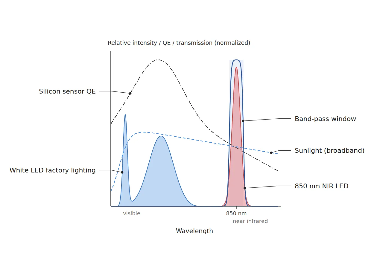
Reason. Factory white LED lighting concentrates most of its emitted energy in the visible band, so almost none of it passes a band-pass filter centered at 850 nm. Sunlight and halogen or incandescent sources, by contrast, contain ample near-infrared components that remain inside the filter passband. The second axis for reducing this residue is time. Ambient light is integrated over the entire exposure time, while strobe lighting concentrates its energy within a short pulse. Cutting the exposure from 10 ms to 200 µs reduces the integrated ambient light to 1/50, and if the pulse energy is the same, the inspection lighting signal is maintained.
Example. If a station near a window still shows a fluctuating background level in the afternoon with only the band-pass filter fitted, the sunlight component inside the passband should be suspected. Narrowing the time axis with a short strobe-synchronized exposure, and blocking the space axis as well with a shading curtain or hood, reduces the residual fluctuation. If needed, the remaining ambient light can be estimated and subtracted from the difference between a lighting-on frame and a lighting-off frame, but this is only an auxiliary means of trimming a residue that has already been reduced optically, and it cannot replace shading.
Point. Ambient light countermeasures must be designed as the product of wavelength (band-pass) × time (strobe) × space (shading), and if any one axis is missing, the gain of the other two is cut by that much.
3. NIR Transparency of Inks and Dyes — Erasing the Visible Pattern and Keeping Only What Is Needed
Point. Another value of NIR lighting is not interference blocking but contrast rearrangement.
Reason. Some organic dye-based inks and colorants strongly absorb a particular color in visible light but absorb weakly in the near infrared and look almost transparent. Carbon black-based inks, on the other hand, absorb broadly from visible to near infrared. So in an 850 nm image, the color-printed background fades or disappears, and only codes and markings printed with carbon-based ink remain dark. On the same principle, a thin translucent molded cover tinted with dye gains higher transmittance in NIR and can reveal foreign matter or assembly status beneath the cover.
Example. When reading a lot code on a molded-part label printed with a color pattern, code dots and the background pattern mix in brightness in the visible image, and the missing-dot decision wavers. When the background pattern disappears in the NIR image, a missing dot becomes a simple blank on a uniform background. Conversely, if the code itself was printed with a dye-based ink, the code also disappears in NIR, with a fatal result. The NIR absorption of inks and dyes varies greatly with formulation, and glossy printed surfaces mix diffuse and specular reflection, so the outcome cannot be confirmed before sample testing.
Point. The first item to check before introducing NIR is not the lighting specification but “the material composition of what must disappear and what must remain”.
In an NIR image, what was visible disappears and what was hidden appears. Confirm first what will disappear.
4. Core Framework — Matching Table
| Category | Item | Specification / Parameter | Basis & Notes |
|---|---|---|---|
| ① Minimum defect size | Missing dot in carbon-ink code | Diameter 150 µm or more | Design assumption. About 4.6 px at 32.7 µm/px |
| ① Minimum defect size | Foreign matter under dye-tinted translucent cover | Diameter 200 µm or more | Design assumption. About 6.1 px |
| ① Minimum defect size | Scratch on printed surface | Width 100 µm or more | Design assumption. About 3.1 px, at the detection boundary |
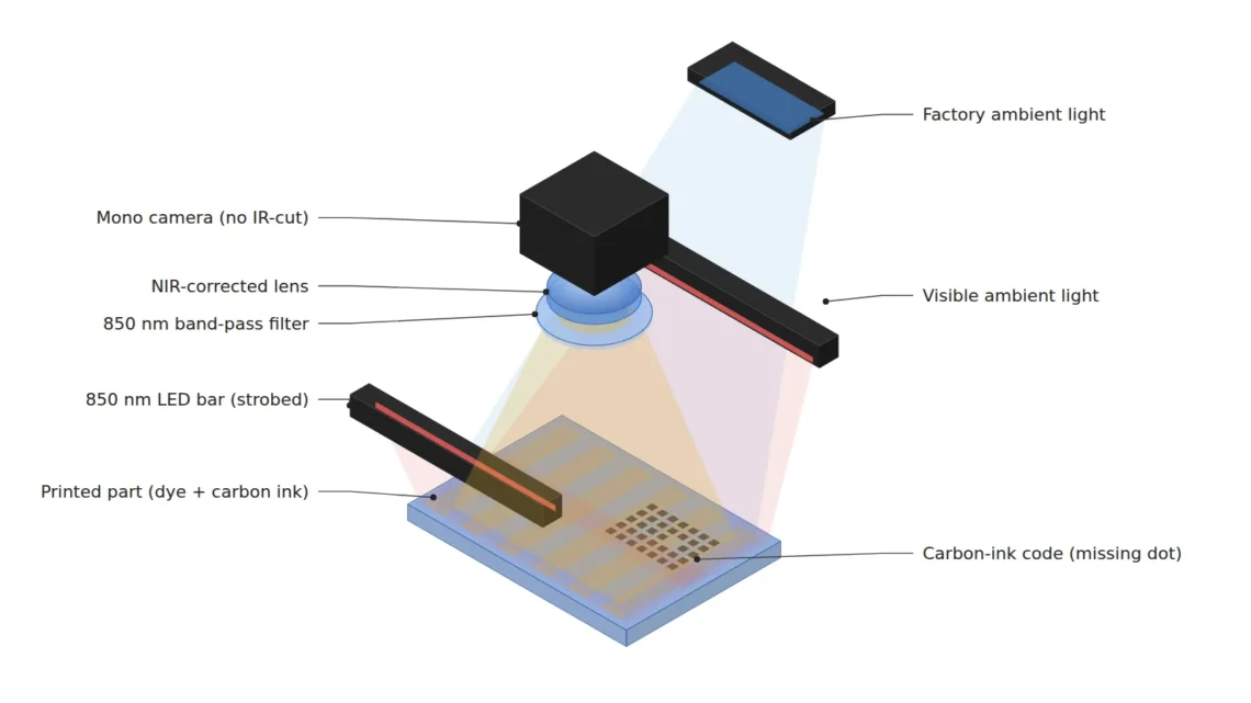
| ② Optical setup | Lighting | Two 850 nm band LED bars, 30° incidence, 200 µs strobe | Design assumption. Exposure-synchronized, minimizes ambient integration |
| ② Optical setup | Filter | Band-pass, center 850 nm, FWHM 50 nm | Design assumption. Mounted in front of the lens |
| ② Optical setup | Camera & lens | Mono 2448 × 2048 px (3.45 µm pixels) without IR-cut filter, NIR-corrected lens with 25 mm focal length | Quantum efficiency at 850 nm assumed at about 40% of the visible peak |
| ② Optical setup | WD (working distance) | 240 mm or more must be secured | Thin-lens object distance about 262 mm (calculated). Measure including filter holder and LED bar bracket interference |
| ② Optical setup | FOV & pixel resolution | FOV 80 mm × 67 mm, 32.7 µm/px | Calculated as 80 mm ÷ 2448 px |
| ② Optical setup | Ambient conditions | Factory lighting 500 lx + daylight from windows | Daylight within the filter passband is handled by shading |
| ③ Algorithm | Ambient difference | Two-frame difference with lighting ON/OFF | Auxiliary step for estimating residual ambient light |
| ③ Algorithm | Flattening | Flat-field correction with an NIR image of a white reference plate | Corrects the illuminance distribution of the two LED bars |
| ③ Algorithm | Detection | Missing dot: blank blob vs. grid ≥ 4 px; scratch: line filter σ = 1.5 px | Design assumption. Retuned against good parts |
Table implication. 80 mm ÷ 2448 px gives a pixel resolution of 32.7 µm/px, and 2048 px vertically × 32.7 µm ≈ 67 mm matches the FOV. The 150 µm missing dot (about 4.6 px) and the 200 µm foreign matter (about 6.1 px) have margin, but the 100 µm scratch, at about 3.1 px, sits right on the boundary of the detection premise. Add the MTF loss from NIR crosstalk, and the effective margin shrinks further. Reducing the FOV to 60 mm gives 24.5 µm/px and about 4.1 px, so you must choose FOV reduction to keep the scratch specification, or a relaxed scratch specification to keep the FOV.
5. When the Opposite Approach Wins
- When color itself is the decision criterion: Print color differences or tinting defects lose their information in a monochrome NIR image. Visible-light color imaging is favorable.
- When the resolution of fine scratches is the top priority: Shorter wavelengths are favorable in terms of the diffraction limit and pixel crosstalk. Short-wavelength lighting such as blue can give sharper edges.
- When strong sunlight enters an open environment where shading is impossible: The daylight component inside the passband remains and the band-pass gain shrinks. Securing a shading structure first or raising the strobe output is more realistic.
The NIR absorption of inks and dyes, diffuse reflection from glossy printed surfaces, and the amount of daylight entering the site vary with formulation and installation position, so the outcome cannot be confirmed before sample testing.
Field Note
At a window-side station on a high-speed assembly line, I once switched lot code inspection on color labels to 850 nm lighting with a band-pass filter. As the background pattern disappeared, the missing-dot decision became noticeably more stable, but the background level still fluctuated when afternoon sunlight came in. Only after switching to a 200 µs strobe-synchronized exposure and attaching a shading hood on the window side did the variation across the day shrink. Another time, on labels from a new supplier, the code ink almost vanished in NIR and the read rate dropped; since then, I ask for NIR sample images first whenever the material changes.
Field Checkpoints
- Is a WD of 240 mm or more secured by actual measurement? — Check including interference from the band-pass filter holder and LED bar brackets.
- Have you first identified the target surface material and reflectance? — The LED bar incidence angle depends on whether it is a glossy printed surface or a matte molded surface.
- Have you confirmed with samples that the code and marking ink that must remain is carbon-based, and that the pattern that must disappear is transparent in NIR?
- Have you confirmed that the camera has no IR-cut filter and that focus was set under 850 nm lighting?
- Have you measured the background level of a lighting-off frame at the brightest time of day? — This checks the daylight residue inside the passband.
- Are the strobe pulse width and the exposure window precisely synchronized?

Noctvision
A machine vision engineer who fits cameras, lenses, lighting, and image-processing algorithms together for a living. Years spent on continuous production lines, vibration, heat, and dust included, working through diffuse reflection, contrast, and resolution differences too fine for a spec sheet to capture inform every post here, closing the gap between theory and the shop floor. Off duty, that same eye for light and lenses goes into repairing fully mechanical vintage film cameras.


You May Also Like
Specular Reflection Erases Defects: How Cross-Polarization Catches Missed Detections on Highly Reflective Surfaces
Software-Defined Lighting: One Head, Switching Between Dark-Field and Coaxial Illumination