Why a Line-Scan Camera Chosen by Line Rate Alone Misses Defects
OPTICS
Line rate is a result that speed sets, and defects are caught by TDI stage count and speed stability.
With an 8K TDI camera scanning a green solder-mask PCB at 400 mm/s, I calculated the light each pixel receives and the blur that a sync error creates.
About 11 min read
When choosing a line-scan camera1, the first number that catches the eye on the spec sheet is the line rate2. The target is a PCB panel covered in green solder mask. Solder mask is a semi-gloss resin that bounces part of the light back as specular reflection and scatters the rest, and I assume a diffuse reflectance of around 10 %. The copper pads exposed between the mask openings are close to mirrors, so their brightness swings widely with the lighting angle. The defect to find is a copper residue 30 μm wide left between pads, and the panel is assumed to pass under the camera at 400 mm/s.
A common choice is to buy a camera with a high maximum line rate and run it at that value. Raising the line rate, though, shortens the time spent on each line, so less light reaches each pixel, and a line rate that does not match the speed stretches or squeezes the image along the travel direction. In a light-starved image, the brightness difference of the residue sinks into noise, and in an image with the wrong length, the pad-spacing rule points at the wrong places. Either way, the cost comes back as defective boards flowing into the good-parts box.
I settle a line-scan setup with three calculations: the line rate that speed and pixel size decide, the number of TDI3 stages needed to fill one pixel with light at that line rate, and the blur that speed wobble creates inside the TDI. The sensor is assumed to be an 8,192 px TDI line sensor with 5 μm pixels.
Two numbers that set the line rate
My rule is that a defect should span at least three pixels before I trust that I can see it, so for a 30 μm residue one pixel on the object is 10 μm, and making that with a 5 μm sensor pixel takes a magnification4 of 0.5. The field of view is 8,192 × 10 μm = 81.92 mm wide, which comfortably covers one strip of a PCB panel. The sensor is 40.96 mm long, so the lens image circle has to be larger than that as well.
Pixel size along the travel direction is set by time, whatever the lens. For the panel to advance exactly 10 μm per line while it moves at 400 mm/s, the camera needs 40,000 lines per second, or 40 kHz, and each line gets 25 μs. Line rate is a value you calculate by dividing speed by pixel size, and it is not something you pick from a catalog. Run a 100 kHz camera at its full 100 kHz and the down-web pixel shrinks to 4 μm, the image grows 2.5 times longer, the data grows 2.5 times, and the exposure per line drops to 10 μs.
Filling a pixel with light inside 25 μs
25 μs is a short time. At the same speed, an area camera with a strobe would need a 12.5 μs exposure to keep motion blur within half a pixel (5 μm), so one line-scan line gets twice that, yet it is still tight for filling one pixel with the light that comes back from semi-gloss solder mask. Turning the lighting up runs into the walls of heat and LED lifetime.
TDI solves this by shooting the same object point again and again over several lines. The sensor stacks N lines, and every time the object advances one pixel, the accumulated charge also shifts one line onward and adds fresh light. A Basler explainer describes these stages as numbering 16 to 256 depending on the camera, with sensitivity rising in proportion to the stage count. With 64 stages, the exposure one point receives becomes 25 μs × 64 = 1.6 ms, gathering 128 times more light than an area strobe held to half-pixel blur. Where photon count decides the signal, shot noise5 makes the signal-to-noise ratio improve by the square root of the stage count, eight times for 64 stages.
40kHz
Line rate from 400 mm/s divided by a 10 μm object pixel
1.6ms
Exposure that 64 TDI stages gather on one point
0.64px
Smear across 64 stages when speed wobbles by 1 %
A 1 % speed wobble smears 64 stages by 0.64 pixel
TDI does not hand out light for free. The N exposures stack on the same point only when the moment the charge shifts one line matches the moment the object advances one pixel; with the line rate fixed at 40 kHz and the actual speed 1 % faster, the object travels 0.64 pixel further over 64 lines. The charge packet collects an image smeared that much along the travel direction, which is 6.4 μm of blur at a 10 μm pixel. At 2 %, it is 1.28 pixels, or 12.8 μm, reaching 43 % of the 30 μm residue width.
So I work out the usable TDI stage count backward from speed stability. With the allowed smear set at 0.3 pixel, the maximum stage count is 0.3 divided by the speed error: 30 stages at 1 %, 60 at 0.5 %, and 150 at 0.2 %. Using 64 stages requires the speed error to stay within 0.47 %. Raising the stage count has to come with proof that the speed is that even. The usual approach builds the line trigger from encoder6 pulses on the moving axis, tying line spacing to distance traveled instead of time, and the Basler material also describes a frame grabber generating precise line triggers from encoder signals. Making the speed itself even on the mechanical side needs a separate review.
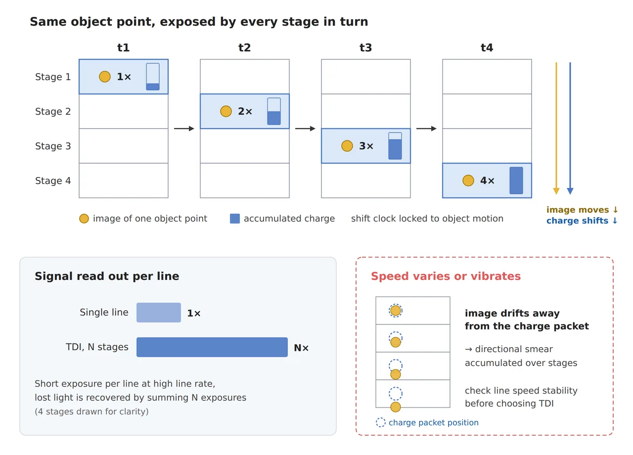
The upper part of the figure shows the image of one point moving down from stage 1 to stage 4 together with the charge, stacking exposure when speed and charge transfer match; the lower part shows image and charge drifting apart when speed slips, producing smear along the travel direction. Because the smear appears only along the travel direction, an image whose cross-web edges stay crisp while only the down-web edges thicken is a reason to suspect synchronization before the lens.
Closing the aperture costs TDI stages
The same light budget hangs over the lens. The Nyquist frequency7 of a 5 μm pixel sensor is 100 lp/mm, and treating the 30 μm residue as one half-period of a bright-dark pair puts it at 16.7 lp/mm on the object and 33.3 lp/mm on the sensor. My criterion is an MTF8 of at least 50 % at 33 lp/mm on the sensor side and at least 20 % at 100 lp/mm. At a magnification of 0.5, the working F-number is approximately 1.5 times the aperture setting, so f/4 works out to 6, and the diffraction-only MTF ceiling is 86 % at 33 lp/mm and 59 % at 100 lp/mm. A real lens adds aberrations and comes out below this ceiling.
PCBs warp, which makes widening the depth of field tempting. With the allowed blur set at one pixel, the depth of field9 is 0.24 mm at f/4 and 0.48 mm at f/8. The moment you close down to f/8, though, the light falls to a quarter, which is the same as cutting 64 TDI stages down to 16. The diffraction ceiling at 100 lp/mm also drops to 23 %, right against my 20 % criterion, and adding aberrations easily pushes it below. At f/11 the ceiling at 100 lp/mm is 3 %, so pixel-sized edges practically vanish. Aperture and TDI stages trade in the same currency.
Gathering the calculations into one table gives the result below. The lens is assumed to have a 60 mm focal length, and the WD10 comes to about 180 mm by thin-lens approximation. The lighting is a coaxial line light11 that makes the copper pads stand out brightly.
| Inspection item | ① Minimum defect size | ② Optical setup · WD | ③ Algorithm parameters · in plain words |
|---|---|---|---|
| Copper residue between pads | 30 μm = 3 pixels (10 μm object pixel) | 8K TDI with 5 μm pixels, magnification 0.5, field of view 81.92 mm, 60 mm lens at f/4, WD about 180 mm (thin-lens approximation), coaxial line light | Line rate 40 kHz (400 mm/s ÷ 10 μm), encoder line trigger, 64 TDI stages, bright blobs of 9 pixels or more + pad-spacing rule |
| Down-web smear | Allowed 0.3 pixel = 3 μm | Same setup, smear = stage count × speed error | At 64 stages, speed error 0.47 % or less; in free-run with 1 % error, drop to 30 stages or fewer |
| Board warp and focus | Allowed blur 1 pixel = 5 μm on the sensor | Depth of field 0.24 mm at f/4, 0.48 mm at f/8 (a quarter of the light, diffraction ceiling 23 % at 100 lp/mm) | If f/8 is needed, raise TDI stages or lighting fourfold, and if neither is possible, reduce warp in the fixture |
Read the three rows together and the line rate turns out to be a result fixed by speed and pixel size, while whether the defect gets caught depends on TDI stage count, speed stability and aperture meshing inside one light budget. The data comes to 8,192 px × 40 kHz = 327.68 MB per second, comfortably inside one 10GigE link (1.25 GB per second), and one 300 mm panel is captured in 0.75 seconds as 30,000 lines, or 245.76 MB.
Where an area camera wins
Line scan with TDI is not always the answer. If the part is small enough to fit in one field of view and can be stopped, an area camera with a strong strobe is simpler, with no speed synchronization to worry about. On a line where the moving axis cannot carry an encoder and speed wobbles by more than 1 %, TDI has to be held below 30 stages, so a plain line-scan camera with stronger lighting is sometimes the better choice. Conversely, when a wide panel must be scanned without stopping and light is short, TDI has the advantage in my judgment. How cleanly the specular reflection of the copper pads separates from the residue under a coaxial line light depends on the surface finish, so it cannot be guaranteed before a sample test.
Looking at camera prices alone, models with a higher maximum line rate cost more, and models with more TDI stages cost more still. By the calculation above, though, 40 kHz is enough for this panel, and making 64 stages pay off means budgeting for the encoder and speed stability as well. Calculating the relationship between speed, pixel and light, in place of chasing the big numbers on the spec sheet, changes the order of the equipment quote. This article explains technology and is not investment advice. See our Disclaimer.
Field Note
Setting up a station for this panel, I would start with a speed log before choosing the TDI stage count. I count the encoder pulses on the moving axis in one-second windows to find the largest speed error, then divide 0.3 by that value and write down the upper limit on usable stages. Next, I shoot the same board once each at 16, 32 and 64 stages and compare the brightness difference and noise around the residue side by side, and if only the down-web edges thicken at 64 stages, I suspect synchronization before the stage count. For the aperture, I start at f/4 and close it one stop at a time only when the measured board warp exceeds 0.24 mm, raising lighting or stages by the same amount.
Field Checkpoints
Once the speed log and the stage-by-stage comparison shots have checked the assumptions behind the calculations, close the setup with the questions below.
- Is a WD of about 180 mm (60 mm lens, magnification 0.5, thin-lens approximation) also secured by the lens datasheet, with enough height left for the coaxial line light to fit in between?
- Is the line rate set to the actual scan speed ÷ the 10 μm object pixel? (Running at maximum line rate shrinks the down-web pixel)
- Is the maximum speed error × TDI stage count 0.3 pixel or less? (0.47 % or less for 64 stages)
- Is the line trigger generated from encoder pulses?
- Does the measured board warp fall within the depth of field of the chosen aperture (0.24 mm at f/4)?
- Have you confirmed the brightness difference between the specular copper pads and the residue on real board samples?
Frequently Asked Questions
Are more TDI stages always better?
For light alone, yes, but smear changes the answer. Doubling the stage count doubles exposure and signal, and it also doubles the smear that the same speed error creates. On a line with large speed error, lowering the stage count and raising the lighting gives a sharper image. With a camera that lets you choose the stage count, I recommend fixing the upper limit from a speed log.
Am I wasting the camera if I run below its maximum line rate?
No. The maximum line rate is only the ceiling that camera can reach, and the value to run is decided by speed and pixel size. The spare margin is what you spend when the speed goes up later. If exposure falls short at the same line rate, though, that margin has to go into TDI stages or lighting.
Glossary
- [1] Line-scan camera line scan
A camera that builds an image by stitching lines from a one-line sensor while the object passes. Used for wide or continuously moving targets. ↩ - [2] Line rate lines per second
The number of lines a line-scan camera captures per second. Pixel size along the travel direction equals speed ÷ line rate. ↩ - [3] TDI time delay integration
A method that shifts charge to the next line each time the object advances one pixel, shooting the same point many times to stack light. Exposure grows with the stage count. ↩ - [4] Magnification m
Size on the sensor divided by size on the object. In the text, 5 μm sensor pixel ÷ 10 μm object pixel = 0.5. ↩ - [5] Shot noise photon noise
Fluctuation caused by photons arriving at random. It equals the square root of the signal, so multiplying the signal by N improves the signal-to-noise ratio by √N. ↩ - [6] Encoder rotary or linear encoder
A sensor that reports distance moved by an axis as pulses. Building the line trigger from these pulses ties line spacing to distance traveled instead of time. ↩ - [7] Nyquist frequency Nyquist limit
The finest line-pair frequency a pixel pitch can represent. For a 5 μm pixel, 1 ÷ (2 × 0.005 mm) = 100 lp/mm. ↩ - [8] MTF MTF
A measure of how much bright-dark contrast a lens preserves at each spatial frequency. The diffraction-only ceiling extends to the cutoff frequency 1 ÷ (wavelength × working F-number). ↩ - [9] Depth of field DOF
The front-to-back distance range on the object side that can be considered in focus. It widens as the aperture closes, at the cost of light and diffraction limit. ↩ - [10] WD WD
The distance from the front of the lens to the object. Room for the lighting has to come out of this distance. ↩ - [11] Coaxial line light coaxial illumination
A line-shaped light that sends illumination down along the lens axis through a half mirror. It shows flat metal surfaces bright and scattering surfaces dark. ↩
References
- Basler, TDI line scan cameras (16 to 256 TDI stages depending on the camera, sensitivity rising with stage count, frame grabbers generating line triggers from encoder signals)
- Edmund Optics, Introduction to Modulation Transfer Function (MTF definition and cutoff frequency ξc = 1 ÷ (λ × f/#))
- Formulas: magnification m = sensor pixel ÷ object pixel, line rate = speed ÷ object pixel, TDI exposure = stage count × line period, smear (pixels) = stage count × speed error, working F-number ≈ f-number × (1 + m), diffraction MTF = (2/π)(arccos x − x√(1 − x²)) with x = spatial frequency × λ × working F-number (λ = 0.55 μm), depth of field ≈ 2 × working F-number × allowed blur ÷ m², WD ≈ f × (1 + 1/m)
Related reading — In the Age of 8K Line-Scan Cameras, the Lens Still Sets the Ceiling on Inspection Resolution · What Optical Design Needs to Not Miss Defects on a High-Speed Line · How Much Closer Does a CIS Sit Than a Line Scan Camera?

Noctvision
An engineer who has handled mechanical design and project management for production equipment since 2005. Here I work through the cameras, lenses and lighting that go into equipment with formulas and public data, and record the assumptions and sources alongside the numbers.


You May Also Like
Coaxial Light Alone Does Not Settle Fine Scratches on Polished Metal
How Much Closer Does a CIS Sit Than a Line Scan Camera?