How to Calculate Machine-Vision Lens Focal Length
OPTICS
Pick a 12 mm lens to see 100 mm across at a 200 mm WD, and the shortcut formula leaves 3.3 mm of margin on each side; solve it again with the thin-lens equation and only 0.13 mm is left.
I worked out the focal length from three values (working distance, field of view and sensor size) and used the same numbers to follow how many pixels a 100 μm defect gets on screen.
About 11 min read
The target is a 100 mm wide stretch of a PCB covered in green solder mask. Solder mask scatters light fairly evenly, but the copper pads and gold-plated contacts that show through it throw light back in one direction like a mirror. The lens calculation ends with the same formula whatever the surface, and once it is done, whether a defect is actually visible is decided by the lighting and the surface. So the first step is to pin down exactly the part that numbers can settle.
Choosing a lens from the catalog by feel shows its cost late. You order a 25 mm lens, find the view too narrow, switch to 16 mm, and machine the camera bracket height twice in between. When one row of parts at the edge of the view slides off the frame, the defects in that row quietly drop out of the inspection, and the rejects come back only after shipping.
Focal length comes out of a calculation. It needs three values and a one-line formula. The common one-line shortcut, though, hides an error as large as the magnification, so I pick candidates with the shortcut and check them once more with the thin-lens equation.
Three values give you the focal length
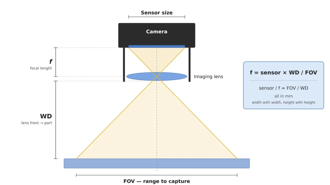
The three values you need are the working distance WD1, the field of view FOV2 that one frame must cover, and the horizontal length of the camera sensor. Sensor sizes are named in inches, like 1/2 inch, but that is a convention3 that does not match the real dimensions, so you have to find the millimeter value in the spec sheet. To see 100 mm across from 200 mm away with a 1/2 inch sensor (6.4 mm wide), the shortcut f ≈ sensor width × WD ÷ FOV gives 6.4 × 200 ÷ 100 = 12.8 mm. That is the required focal length4.
The formula is this simple because of two similar triangles. The distance from the lens center to the sensor and the distance from the lens center to the object share one vertex, so the ratio of sensor width to field of view equals the ratio of those two distances. The reason a 50 mm lens is called standard on a film camera is the same ratio story. On 36 mm wide film a 50 mm lens sees 39.6° across, but put the same lens on a 6.4 mm wide sensor and it sees only 7.3°. A focal length alone does not set the size of the view. It means something only when paired with a sensor.
| Optical format | Width (mm) | Height (mm) | Diagonal (mm) |
|---|---|---|---|
| 1/3 inch | 4.8 | 3.6 | 6.0 |
| 1/2.5 inch | 5.7 | 4.3 | 7.2 |
| 1/2 inch | 6.4 | 4.8 | 8.0 |
| 1/1.8 inch | 7.2 | 5.4 | 9.0 |
| 2/3 inch | 8.8 | 6.6 | 11.0 |
| 1 inch | 12.8 | 9.6 | 16.0 |
| 4/3 inch | 17.3 | 13.0 | 21.6 |
The dimensions in the table are conventional values and differ slightly by manufacturer. Even within 1/2 inch the width changes with the pixel count and pixel size, so it is safer to put pixel size × horizontal pixel count into the calculation. A 1,600 × 1,200 px sensor with 4.0 μm pixels is 6.4 mm wide, which matches the table.
Margin from the shortcut disappears in the thin-lens equation
No lens is sold at 12.8 mm, so you end up choosing between 12 mm and 16 mm. Solved backward with the shortcut, 12 mm gives a 106.7 mm view and 16 mm gives 80 mm, so 16 mm cannot cover 100 mm and 12 mm seems to leave 3.3 mm on each side. Magnification5 is the reason not to stop there. The shortcut assumes the image forms at the focal length, but the closer the object, the further behind the focal length the image forms.
Solved again with the thin-lens equation 1/f = 1/u + 1/v, a 200 mm distance from the lens center to the object needs a focal length of 12.03 mm. The shortcut's 12.8 mm comes out larger by the magnification of 0.064, that is, by 6.4 %. Mount a 12 mm lens at 200 mm as it is and the view is 6.4 × (200 − 12) ÷ 12 = 100.27 mm, leaving only 0.13 mm on each side. That is almost nothing. If the board sits in the fixture just 0.2 mm askew, the edge of the last row of parts leaves the frame.
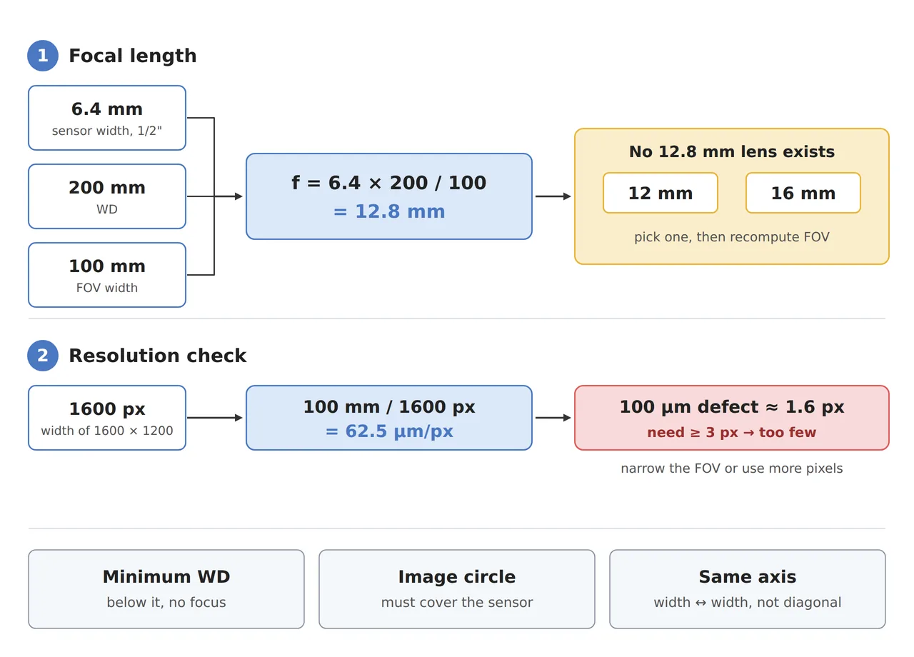
The calculation flow in the figure is the first step, starting from the shortcut. For setups where magnification exceeds 0.1, the two formulas differ by more than 10 %, so it is right to calculate with the thin-lens equation from the start.
Common belief
A 12 mm lens sees wider than a 16 mm lens, so it leaves plenty of margin on a 100 mm view.
Solved again at a 200 mm WD
The 12 mm lens covers 100.27 mm, leaving only 0.13 mm per side, and a board 0.2 mm askew loses its last row.
If it were my setup, I would add 10 mm to the WD and make it 210 mm. With the same 12 mm lens the view becomes 105.6 mm, which leaves 2.8 mm on each side. If you really want a 16 mm lens, a 100 mm view requires raising the WD to 266 mm, and whether there is room to hang a camera at that height is a question the machine drawing answers.
A view that fits still needs its defect pixels counted
A frame of the right size does not mean the inspection works. The length one pixel covers on the object, the object-side pixel resolution6, is the view divided by the horizontal pixel count. A 1,600 px camera looking at 105.6 mm gives 66 μm per pixel, and a 100 μm wide defect spans 1.52 pixels. When a defect spans one or two pixels, its brightness difference splits in half depending on how it overlaps the pixel boundaries, so the same defect shows on one board and vanishes on another. Detection is left to luck.
My rule is that the smallest defect spans at least three pixels. That needs pixels of 33.3 μm or less, and keeping the 105.6 mm view would take 3,168 px across. Assume a switch to a sensor 4,096 px wide with 3.45 μm pixels: the sensor width grows to 14.13 mm, and the focal length has to be recalculated. A 25 mm lens at a 210 mm WD gives a 104.6 mm view and 25.5 μm per pixel, and a 100 μm defect fits into 3.92 pixels.
12.03mm
Required focal length solved with the thin-lens equation (200 mm WD, 100 mm view, 6.4 mm sensor width)
0.13mm
Margin left on each side of the view with a 12 mm lens at a 200 mm WD
3.92px
Pixels a 100 μm defect spans with a 4,096 px sensor and a 25 mm lens at a 210 mm WD
Changing the sensor changes the lens class too. A sensor 14.13 mm wide and 10.35 mm tall has a 17.5 mm diagonal, so the image circle7, the diameter of the circle the lens lights evenly, must be at least 17.5 mm or the four corners go dark. Since the pixels shrank to 3.45 μm, I also check in the lens spec sheet that its resolution class can handle that pixel size. One camera swapped in to give the defect three pixels ends up pushing up the lens diameter and the lens price.
Spec sheet lines to check before ordering
Once the calculation is done, I look for three lines in the lens spec sheet. The first is the minimum object distance8. Every lens has a closest distance at which it can focus, and if the calculated 210 mm WD is shorter than that, the lens cannot focus. The second is the image circle, and the third is the distortion9 at the edge of the frame.
Distortion is the image position drifting slightly from its ideal place toward the edges. Assuming 0.1 % edge distortion, the edge of the 52.3 mm half view moves 52 μm, which is two pixels at 25.5 μm per pixel. For an inspection that only asks whether a scratch is there, a two-pixel shift is no big deal, but for one that measures part positions or dimensions it becomes measurement error directly. For that kind of inspection I would look first at a telecentric lens10, whose magnification stays nearly constant whatever the object distance.
| Setup | ① Minimum defect size | ② Optical setup · WD | ③ Algorithm parameters · in plain words |
|---|---|---|---|
| Shortcut as is | 100 μm = 1.60 px (62.7 μm/px) | 1/2 inch 1,600 px, 12 mm lens, 200 mm WD, 100.27 mm view (0.13 mm margin per side) | Below the three-pixel rule. Board alignment margin runs out before defect judgment even starts |
| WD adjusted only | 100 μm = 1.52 px (66 μm/px) | 1/2 inch 1,600 px, 12 mm lens, 210 mm WD, 105.6 mm view (2.8 mm margin per side) | Alignment margin appears, but defects still fall short of three pixels. Suits defects of 300 μm and up |
| Sensor replaced as well | 100 μm = 3.92 px (25.5 μm/px) | 4,096 px wide with 3.45 μm pixels, 25 mm lens, 210 mm WD, image circle 17.5 mm or more | Minimum defect candidate width 3 px. For judgments that measure position, correct the two-pixel edge shift first |
Reading the table line by line shows that the focal length calculation only fixes the alignment margin in the first row, and fitting the defect into three pixels ends only when the sensor and the lens class change together. On the other hand, for an inspection where defects are 300 μm or larger and only alignment margin is needed, the second row, a 1/2 inch camera with a 12 mm lens at a 210 mm WD, wins on both price and mounting space. Whether contrast actually appears at these pixel counts on strongly glossy spots like copper pads cannot be guaranteed before a sample test.
Work a calculated lens takes off your hands
The lens selection order starts from the smallest defect size and moves down through the pixel size, the pixel count and view, the WD you can install, the focal length, and the actual lens size on the market. I would write this order one line at a time on the first page of the spec, pick the size closest to the calculated value, and confirm the view and pixel count again with the thin-lens equation. If you are just starting, I recommend solving both formulas once by hand with a 1,600 px camera and a 12 mm lens. Seeing the gap between 0.13 mm and 3.3 mm yourself changes how you treat the shortcut.
Finishing the lens calculation at the spec stage is the machine vision engineer’s share of the work, and it cuts down on remachining brackets during commissioning. For the person reading the quote, the lens price is small next to the camera price, but the cost of a wrong lens grows into a sensor swap and fixture rework. This article explains technology and is not investment advice. See our Disclaimer.
Field Note
For a new setup, before ordering the lens I measure whether the machine drawing actually leaves 210 mm between the board top and the camera mounting face. Next I hang a 1,600 px camera temporarily, photograph a ruler, and divide the length shown across the frame by 1,600 to check that one pixel matches the calculated 66 μm. The real principal-plane position of a lens differs from one spec sheet to the next, so a WD measured from the lens front misses the calculation by a few mm, and one ruler photo catches that difference.
Field Checkpoints
Once a ruler photo has confirmed the pixel size, check the numbers you will carry into the spec with the questions below, one by one.
- Is a WD of 210 mm secured inside the machine even after adding the lens and lighting fixtures? (whether there is real height to hang the camera)
- Did you put the sensor width and the view in the same direction into the calculation? (width with width, height with height)
- Is the view solved with the thin-lens equation wider than the board width plus the alignment error? (a 12 mm lens at a 200 mm WD leaves 0.13 mm)
- Does the smallest defect span three pixels or more? (for a 100 μm defect, 33.3 μm per pixel or less)
- Is the lens image circle larger than the sensor diagonal, and is the minimum object distance shorter than the WD? (17.5 mm or more for a 4,096 px sensor)
- Did you confirm with sample photos that contrast appears on strongly glossy pads? (whether you avoid concluding detection from the calculation alone)
Frequently Asked Questions
Can I calculate with the diagonal instead?
If you pair the sensor diagonal with the view diagonal, the formula itself holds. An inspection target, though, usually has a fixed width in one direction, horizontal or vertical, and matching only the diagonal on a 4:3 sensor can leave you short of the width you actually need. Calculating with the dimension in the direction you judge and checking the other direction as a result leads to fewer mistakes.
Can a zoom lens get there without the calculation?
A zoom lens is handy for framing during setup, but if vibration or a stray hand changes the focal length, the pixel size changes with it. On an inspection line it is safer to use a fixed focal length lens and lock the focus ring. If you want to run the view and depth of field together from four values, see the lens calculator article.
Glossary
- [1] WD working distance
The distance from the lens to the surface being inspected. The calculations in the text use the thin-lens approximation and measure from the lens center; real lenses list a separate value from the front of the lens in the spec sheet. ↩ - [2] FOV field of view
The area on the object that one camera frame covers. Width and height are given separately. ↩ - [3] Optical format optical format
The conventional naming of sensor size, such as 1/2 inch or 2/3 inch. The names come from old camera tube diameters, so they do not match the real sensor diagonal. ↩ - [4] Focal length focal length
The distance at which parallel incoming light converges to a point after passing through the lens. On the same sensor, a shorter focal length sees wider. ↩ - [5] Magnification magnification
The size of the image on the sensor divided by the size of the object. Seeing 100 mm with a 6.4 mm wide sensor gives a magnification of 0.064. ↩ - [6] Object-side pixel resolution object-side pixel resolution
The length one pixel covers on the object. It is the view divided by the horizontal pixel count, written in μm/px. ↩ - [7] Image circle image circle
The diameter of the circle the lens can light evenly. If it is smaller than the sensor diagonal, the four corners record dark. ↩ - [8] Minimum object distance minimum object distance, MOD
The closest object distance at which the lens can focus. ↩ - [9] Distortion distortion
How far the image position drifts from its ideal place toward the edge of the frame. Usually given in %. ↩ - [10] Telecentric lens telecentric lens
A lens whose chief rays on the object side run parallel to the optical axis, so the object barely changes size when it moves slightly forward or back. Widely used for dimensional measurement. ↩
References
- Formulas: shortcut f ≈ sensor width × WD ÷ FOV; thin-lens equation 1/f = 1/u + 1/v with magnification m = sensor width ÷ FOV gives f = u × m ÷ (1 + m); view = sensor width × (WD − f) ÷ f; pixel size = view ÷ horizontal pixel count; angle of view = 2 × atan(sensor width ÷ 2 ÷ f)
- Optical format dimensions: the table lists conventional values; real values follow pixel size × pixel count in the camera spec sheet
- Assumed values: a 4,096 × 3,000 px sensor with 3.45 μm pixels and 0.1 % edge distortion are assumptions for the worked example
Related reading — In Machine-Vision Inspection, Physics Comes Before Software · A Machine Vision Lens Calculator That Catches the FOV Error a Shortcut Formula Misses · How Liquid Lens Autofocus Solves Focus on High-Mix, Low-Volume Lines

Noctvision
An engineer who has handled mechanical design and project management for production equipment since 2005. Here I work through the cameras, lenses and lighting that go into equipment with formulas and public data, and record the assumptions and sources alongside the numbers.


You May Also Like
A Mono Camera Catches PCB Color Differences When You Choose the Wavelength
How Much Closer Does a CIS Sit Than a Line Scan Camera?