Why Does One Lighting Angle Decide OCR Read Rates on Molded Characters? — Low-Angle Ring Illumination and Quadrant Lighting Calculated from Character Height and Stroke Spacing
LIGHTING / ALGORITHM
Lot numbers and cavity numbers molded into the surface of an injection-molded part have no color, unlike ink printing. The characters and the background are the same resin and the same color, and the only thing that separates them is a height difference of a few tens of µm. Under illumination that lights evenly from above, these characters are nearly invisible, and the OCR engine, searching for letters in what is practically a blank image, returns the wrong characters.
Left unaddressed, the cost bursts out in traceability. If a cavity number is misread, the mold cavity that produced the defect cannot be identified and every cavity must be stopped, and the process of having people re-read failed parts hardens into a permanent staffing need. History data mixed with misreads is more dangerous than read failures, because wrong records remain as if they were correct ones.
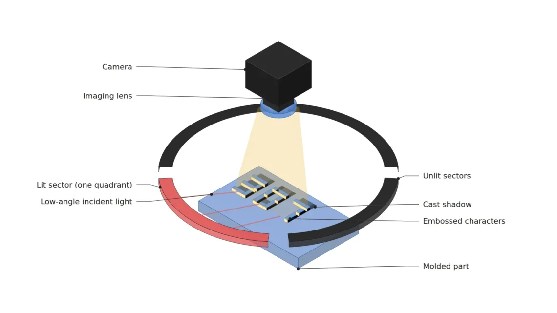
The solution is low-angle ring illumination, which turns height differences into brightness differences. When light is laid down at an angle close to horizontal, one wall of a relief faces the light head-on and brightens, while the opposite side darkens into shadow. This article sets out how to calculate that incidence angle from the character height (µm) and stroke spacing instead of choosing it by feel, and how to recover per-direction contrast with quadrant-segmented lighting.
In colorless characters, what creates contrast is not brightness but the length of the shadow.
1. Low-Angle Lighting Turns Height into Brightness
Point. The role of a low-angle ring light is not to light up the characters but to create a pair of a bright wall and a dark shadow at the edges of the character relief.
Reason. A matte molded surface reflects light diffusely in many directions. In diffuse reflection, surface brightness is proportional to the cosine of the angle between the incident light and the surface normal, so the closer the light is to horizontal, the darker the flat background becomes and the relatively brighter the relief walls facing the light become. At the same time, a shadow forms behind the relief. The brightness difference between flat area and wall, together with the shadow, becomes edge contrast. Under high-angle illumination, both the flat area and the walls are bright and this difference disappears.
Example. Consider a cavity number embossed 50 µm high on a black matte ABS housing. Under a dome or coaxial light the characters and background merge into the same gray, but under a low-angle ring at a 20° incidence angle the outlines of the strokes rise up as pairs of bright and dark lines. However, low-angle lighting also highlights flow marks and fine texture on the molded surface, and on resins with a strong specular component such as glossy PC the wall highlights can saturate, so this cannot be confirmed before sample testing.
Point. A low-angle ring is not a “dim light” but a converter that moves height information into the brightness channel. The variable that sets the sensitivity of that conversion is the incidence angle.
2. Calculate the Incidence Angle from Character Height and Stroke Spacing
Point. The incidence angle (lighting elevation) E is not “the lower the better” but a value chosen so that the shadow length L = h ÷ tan E falls between the detection floor and the stroke spacing.
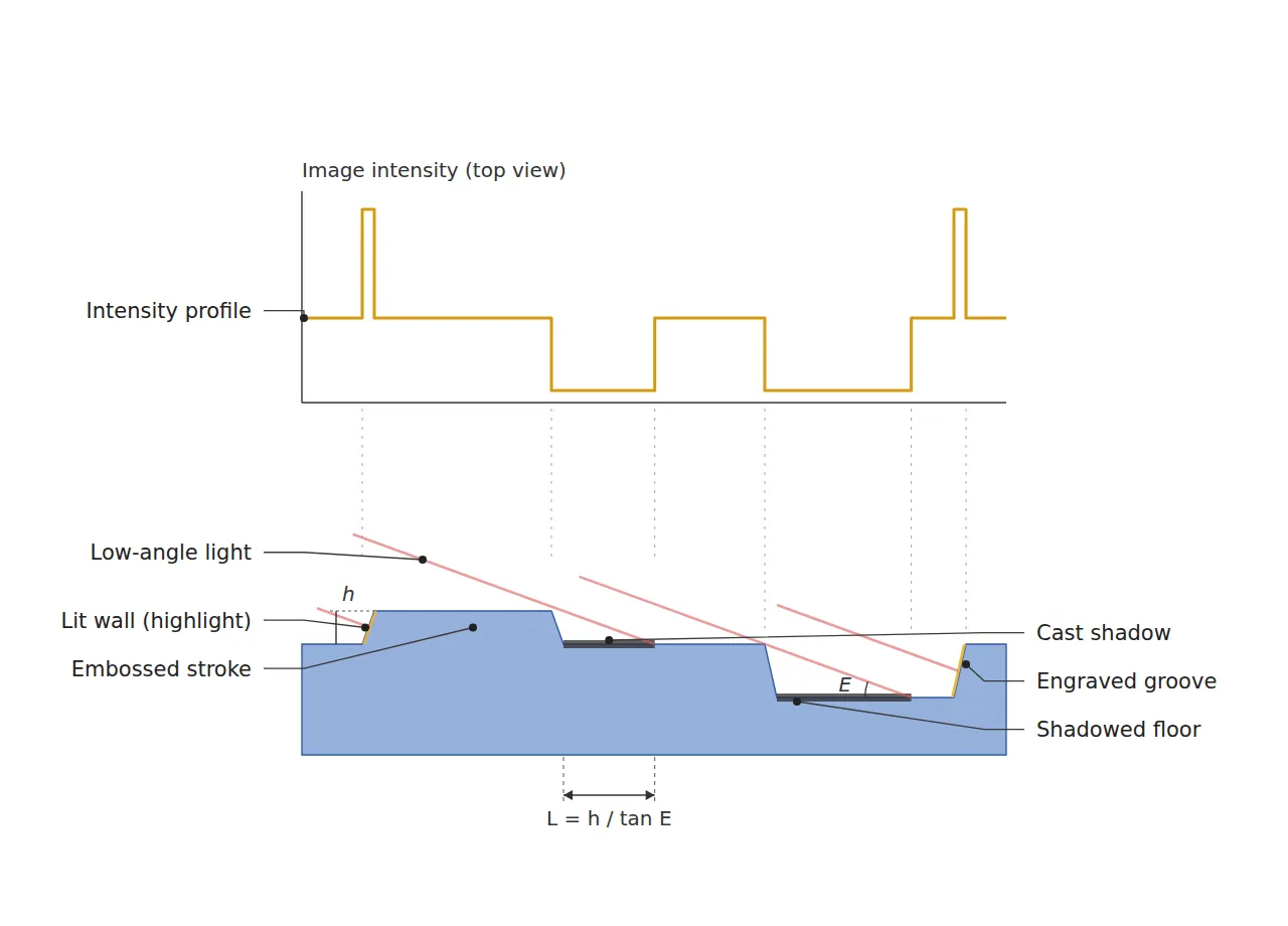
Reason. When a relief of height h receives light at elevation E, a shadow of horizontal length L = h ÷ tan E forms. If the shadow is too short, it covers only a few pixels and is not detected; if it is too long, it covers the gap to the next stroke and two characters merge into one blob. So the lower limit is set as “shadow of 3 px or more” and the upper limit as “shadow no longer than half the stroke spacing”. Solving the upper-limit condition gives a minimum elevation E ≥ atan(h ÷ half the spacing), and this is the core insight of this article. The incidence angle is decided not by a lighting catalog but by the character height and stroke spacing on the drawing.
Example. For characters embossed 50 µm high with a 300 µm stroke spacing, keeping the shadow at or below half the spacing, 150 µm, requires E ≥ atan(50 ÷ 150) ≈ 18.4°, so 20° is chosen. The shadow is then 50 ÷ tan 20° ≈ 137 µm, about 11 px at 12.3 µm/px. Lighting the same characters at 10° stretches the shadow to about 284 µm, covering almost the entire stroke spacing. Conversely, at 20° the minimum height that produces a 3 px (about 37 µm) shadow is about 13 µm, so reading margin remains down to that value even as characters become shallower through mold wear. An 80 µm engraved mark produces a shadow of about 220 µm that stays inside the 300 µm groove width, darkening only part of the groove floor.
Point. When setting the incidence angle, open the drawing before changing the light. With just two values, character height and stroke spacing, the minimum elevation and shadow length are calculated in µm.
If the shadow is short, the characters disappear; if it is long, the characters stick together.
3. Quadrant-Segmented Lighting — Illumination That Restores Direction
Point. Switching on the whole ring at once lets light from all sides fill each other’s shadows, and contrast falls. Dividing the ring into four sectors and lighting them in sequence yields per-direction shadows separately.
Reason. Light from one direction makes the longest shadow at edges perpendicular to that direction and almost no shadow at edges parallel to the light. With the whole ring on, the light that illuminates the left wall simultaneously fills the shadow of the right wall, so the bright-dark pair at each edge is diluted. Switching the north, south, east and west sectors on separately to take four images, then combining the differences of opposing sectors (north−south, east−west), cancels the flat background and leaves only the edges. A practical advantage is that differences alone are enough, without any calculation to recover surface normals.
Example. With a ø120 mm ring placed about 21.8 mm above the part, the elevation at the center of the FOV is 20°. At both ends of a 30 mm FOV, however, the elevation spreads to about 25.9° toward the near LEDs and about 16.2° toward the far ones, so the shadow length wavers between about 103 and 172 µm. The far-side 172 µm exceeds 150 µm, half the stroke spacing, so shading correction must be applied separately per sector and the reading confidence of characters at the FOV edge must be managed separately. Four exposures lengthen the cycle time, and registration error can arise from part movement between exposures. Transport synchronization itself requires a separate review.
Point. The value of quadrant lighting lies not in brightness but in edge direction information. Software compositing is meaningful only when this direction information has been secured at the lighting stage; a shadow that has vanished from a single all-on image cannot be revived by an algorithm.
4. Core Framework — Matching Table
| Category | Item | Specification / Parameter | Basis & Notes |
|---|---|---|---|
| ① Minimum defect size | Character relief to read | Embossed height 50 µm, engraved depth 80 µm, stroke width and spacing 300 µm | Design assumption. Character height 2.0 mm (about 163 px) |
| ① Minimum defect size | Missing stroke (short shot) | Length 60 µm or more | Design assumption. Occupies about 4.9 px |
| ① Minimum defect size | Minimum readable relief height | About 13 µm | Calculated value. 3 px (about 37 µm) × tan 20° |
| ② Optical setup | Illumination | Low-angle ring ø120 mm, mounted about 21.8 mm high, 4-sector sequential lighting | Elevation at FOV center 20°. At or above the minimum elevation of 18.4° (calculated) |
| ② Optical setup | Shadow length | Embossed about 137 µm (about 11 px), engraved about 220 µm (about 18 px) | Calculated value. L = h ÷ tan E. Embossed 103–172 µm at FOV-edge elevations of 16.2–25.9° |
| ② Optical setup | Lens | Focal length 35 mm, F/8 | Design assumption. Thin-lens object distance about 159 mm (magnification 0.28×) |
| ② Optical setup | WD (working distance) | 140 mm or more must be secured | Measured from the front of the lens barrel. Confirm by measurement that the ring top does not interfere with the barrel |
| ② Optical setup | Sensor & FOV | 2448 × 2048 px (3.45 µm pixel), FOV 30.0 mm × 25.1 mm, 12.3 µm/px | Calculated value. 30.0 mm ÷ 2448 px |
| ③ Algorithm | Shading correction | Individual flat-field per sector using a character-free reference surface image | Removes the brightness gradient caused by elevation spread within the FOV |
| ③ Algorithm | Direction compositing | Per-pixel maximum of |north−south| and |east−west| differences | Flat background cancels, only edges remain |
| ③ Algorithm | Binarization | Adaptive binarization window 75 px | About 3 times the stroke width of about 24.5 px |
| ③ Algorithm | OCR decision | Normalize the 163 px character height to 32 px, re-read below confidence 0.90 | Design assumption. Withholding a reading takes priority over misreading |
Table implication. At 12.3 µm/px, a 300 µm stroke width is about 24.5 px and a 60 µm missing stroke about 4.9 px, so there is headroom in resolution. The real bottleneck of this setup is not resolution but the elevation spread at the FOV edge. A shadow of 137 µm at the center grows to 172 µm at the far edge and exceeds half the stroke spacing, so to make reading quality uniform, a design trade is needed: place the characters near the center of the FOV, or enlarge the ring diameter to reduce the spread.
5. When the Opposite Approach Wins
- When characters and background differ in color or gloss: Characters whose surface color has changed, as in laser marking, need no height information. A diffuse dome or coaxial light produces a cleaner image without texture noise.
- Parts whose surface texture is rougher than the characters: Coarse texture such as grained finishes casts stronger shadows than the characters under low-angle light. A 3D method that measures height directly can be advantageous.
- Lines with no slack in cycle time: If four quadrant exposures are impossible, a single image under a one-direction low-angle bar light aligned with the character direction is a realistic compromise.
The benefit of low-angle lighting varies greatly with resin type, gloss and surface texture, so which method wins cannot be confirmed before sample testing.
Field Note
When reading cavity numbers on molded housings on a high-speed assembly line, I first used a low-angle ring with all segments on and tried simply lowering the elevation. Bringing the elevation down to around 10° sharpened the shadows, but digits with narrow stroke spacing began to stick together and confusion between “8” and “0” increased. Only after resetting the elevation to around 20° from the embossed height and stroke spacing on the drawing, and applying quadrant lighting with difference compositing, did the reading stabilize. Even so, characters at the FOV edge still came out with low confidence, so we moved the layout toward the center, and I believe this setting should be re-checked again on parts where mold wear has progressed.
Field Checkpoints
- Is a WD of 140 mm or more secured by actual measurement — check including interference between the front of the lens barrel, the top of the ring light and the top of the part.
- Have the surface material and reflectance of the target been identified first — the effect of low-angle light differs for matte resin, glossy resin, or grained texture.
- Has the minimum elevation atan(h ÷ half the spacing) been calculated from the character height and stroke spacing on the drawing.
- Is the shadow length at least 3 px and no more than half the stroke spacing — check it at the FOV-edge elevations as well.
- Have shading correction images been acquired separately for each quadrant sector.
- Do the four exposures fit within the line cycle time.

Noctvision
A machine vision engineer who fits cameras, lenses, lighting, and image-processing algorithms together for a living. Years spent on continuous production lines, vibration, heat, and dust included, working through diffuse reflection, contrast, and resolution differences too fine for a spec sheet to capture inform every post here, closing the gap between theory and the shop floor. Off duty, that same eye for light and lenses goes into repairing fully mechanical vintage film cameras.


You May Also Like
Automotive Part Appearance Inspection: Lighting Design Comes First
Shorter Exposure Means a Darker Image, So How Do You Freeze Motion? — Suppressing Motion Blur on the Move with Strobe Overdrive