The Vision Decision Is Done — So Why Does the PLC Learn It Late? Breaking Down Trigger-to-Output Latency on the Vision Side
EDGE AI / INTERFACE
The inspection log says the verdict finished in a few milliseconds, yet the machine side says the result arrived late. The vision engineer shows the inference time, and the controls engineer shows the time the result was received. The gap between the two numbers is in nobody’s log.
Left alone, this gap becomes serious the moment a late result is read as another part’s result. If the result carries no number that identifies the part, one delayed result shifts the verdicts of the parts that follow, one after another, and a defect passes while recorded as good.
The fix is to split the path from trigger to result output into segments on the vision side, measure the worst case of each, and send every result with a trigger number and a timestamp. How often the PLC reads the result and its logic belong to the PLC-side design, are outside the scope of this article and need a separate review. This article covers only the segments the vision system can be responsible for.
Results must be matched not by “when did it arrive” but by “which trigger is it for”.
1. Vision-Side Latency Is the Sum of Six Segments
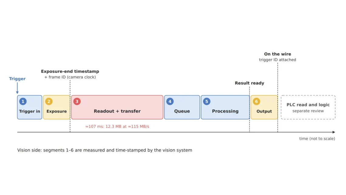
Point. Vision-side latency is not the inference time but the sum of six segments from trigger input to result output.
Reason. ① trigger input (input filter and delay), ② exposure, ③ sensor readout and transfer (interface bandwidth), ④ queue (waiting while the previous image is processed), ⑤ processing (preprocessing, inference, decision), ⑥ result output (digital output or network message). This is the same view as the p99 latency budget article, which splits the latency budget into stages; here the focus is on ⑥, where the result leaves the vision device, and on identifying the result.
Example. The benchmark inference time is only part of ⑤, and ③ is set by image size and link bandwidth. One 4096 × 3000 px 8-bit image is about 12.3 MB, so over a 1GigE link with an effective rate of about 115 MB/s (interface bandwidth article) the transfer alone takes about 107 ms.
Point. Only with timestamps at the start and end of each segment can you say “where it got late”. Using the timestamp and frame ID carried by the camera’s exposure end event (the Exposure End event in GenICam SFNC) as the reference point records the boundary between ② and ③ on the camera clock.
2. Result Output Paths — Digital Output vs. Network Message
Point. Whether the result goes out as a digital output signal or as an industrial Ethernet message changes the shape of the worst-case latency.
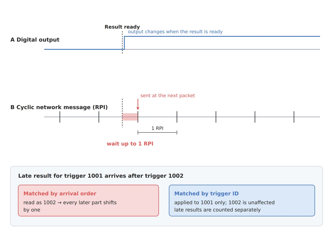
Reason. A digital output is carried over the wiring the moment the vision device changes it, so vision-side latency closes at the moment the output is updated. By contrast, an EtherNet/IP I/O connection set to a Cyclic trigger sends data at a fixed interval called the RPI (Requested Packet Interval) (ODVA). Even right after a result is ready it may wait until the next transmission, and in the worst case that wait approaches one full interval.
Example. Assuming an RPI of 10 ms, a wait of 0 to about 10 ms can be added before the result is sent, depending on when processing finishes. On top of that comes the moment the PLC reads the data in its logic, which is part of the PLC-side design and needs a separate review. For reference, IEC 61131-3 is often mentioned when PLC communication delay is discussed, but that standard covers PLC programming languages; communication is covered by Part 5 (Communications) of the same series.
Point. The vision side is responsible for recording, separately, the time a result was ready and the time it actually went onto the link. If results are close to the deadline, consider splitting the path — the verdict bit on a digital output and detailed data over the network — before shortening the network interval.
3. Attach a Trigger Number to Every Result — The Trap of Matching by Time
Point. Every result message must carry, along with the verdict, a trigger number (or frame ID) and the exposure timestamp.
Reason. In a system whose processing time wavers, the assumption “the next result to arrive = the next part’s result” collapses with a single delay. With a number, the receiver can match a late result exactly to its part or explicitly separate a result that missed the deadline as “no verdict”. GenICam SFNC defines a feature that carries a timestamp and frame ID together in the exposure end event, and IEEE 1588 (PTP), integrated into GigE Vision 2.0, lets the clocks of multiple devices be synchronized so timestamps can be compared on the same time axis.
Example. Even if the result for trigger 1001 misses the deadline and arrives after trigger 1002, the number makes it apply only to part 1001 and keeps it from mixing with the verdict for 1002. Without the number, the receiver may read this result as belonging to 1002, and from that moment on a matching shifted by one position continues.
Point. How to handle results that missed the deadline is a decision on the machine side, but the numbers and times that make that decision possible must come from the vision side.
4. Core Framework — Matching Table
| Category | Item | Spec / Parameter | Basis / Note |
|---|---|---|---|
| ① Minimum defect size | Minimum defect | 100 µm | Design assumption. About 4.1 px at 24.4 µm/px — cutting resolution as a latency fix consumes this margin first |
| ② Optical setup | Sensor / image size | 4096 × 3000 px, 8-bit (about 12.3 MB per image) | Sets the size of transfer segment ③ |
| ② Optical setup | Interface | 1GigE, effective about 115 MB/s | About 107 ms per image for transfer alone |
| ② Optical setup | WD (working distance) | Object distance about 202 mm per the lens calculator example; confirm the real WD with maker data | Fix it on the drawing so exposure conditions hold after reinstallation |
| ③ Algorithm | Timestamp reference | Exposure end event timestamp + frame ID | GenICam SFNC, boundary of segments ② and ③ |
| ③ Algorithm | Result message fields | Verdict, trigger number, exposure timestamp, processing done time | Number matching on the receiving side |
| ③ Algorithm | Output path | Verdict bit on digital output, detailed data over the network (RPI 10 ms assumed) | Worst network wait about 1 RPI |
| ③ Algorithm | Monitoring metrics | p99 latency per segment, count of deadline misses | Do not judge by the average alone |
Table insight. Under this example’s conditions the longest segment is not inference but transfer (about 107 ms). The cyclic wait of a network output is at most one RPI, but the transfer segment repeats for every image, so the priority of fixes under these conditions is transfer → queue → output path. Reducing transfer time by cutting resolution directly consumes the ① margin of about 4.1 px, so it is the last option.
5. Conditions Where the Opposite Approach Wins
- Simple inspections that need only one verdict bit: when processing always finishes within one trigger interval, building with only a hardware trigger and digital output, without number matching, is simpler and easier to verify.
- Several cameras used at the same time: instead of wiring a trigger to each camera, synchronizing clocks with PTP and triggering over Ethernet with a Scheduled Action Command reduces wiring.
- Offline inspection with ample processing margin: breaking down the segments drops in priority.
Trigger input stability and exposure conditions are also affected by the reflective properties of the target surface, so the actual latency distribution cannot be guaranteed before a sample test.
Field Note
The processing times in the vision log always had margin, yet the machine-side records occasionally showed verdicts shifted by one position. The result messages had no number, so a result delayed once by the transfer queue was being read as the next part’s verdict. Once the results carried the trigger number and exposure time, the shift disappeared, and late results were counted separately, which even confirmed that the cause was the transfer queue. Since then, when defining a result format, I write the number field before the verdict.
Field Checkpoints
- Are the WD and lighting space fixed? — fix them on the drawing so the WD and exposure conditions (exposure time, light level) do not change after reinstallation.
- Are start and end timestamps recorded for each of the six segments?
- Do result messages carry the trigger number (frame ID) and the exposure timestamp?
- For network output, is the RPI (update interval) known and is the worst-case wait of one interval in the budget?
- Are decisions based on p99 and the count of deadline misses rather than the average?
- Has the boundary that PLC-side read interval and logic delay need a separate review been agreed in writing?
References
- ODVA — EtherNet/IP Quick Start for Vendors Handbook (PUB00213R0) — RPI definition (p.25), Cyclic trigger (p.11 Table 1)
- EMVA — GenICam SFNC v2.7 — Timestamp (3.66), Exposure End Event (15.5)
- LUCID — Multi Camera Synchronization using PTP and Scheduled Action Commands — PTP (IEEE 1588) integrated into GigE Vision 2.0
- IEC 61131 (Wikipedia) — Part 3 Programming languages, Part 5 Communications
Related reading — Is It Safe When the Average Latency Fits the Deadline? — Breaking Down the Edge Vision Inspection Latency Budget by p99 · Camera Interface Bandwidth Determines Resolution — From GigE Vision to CoaXPress 2.0 · Edge AI Inference Latency: The Camera Interface Decides Before the NPU Does — GigE Vision 3.0 RDMA and Disaggregated Inspection Architecture

Noctvision
A machine vision engineer who fits cameras, lenses, lighting, and image-processing algorithms together for a living. Years spent on continuous production lines, vibration, heat, and dust included, working through diffuse reflection, contrast, and resolution differences too fine for a spec sheet to capture inform every post here, closing the gap between theory and the shop floor. Off duty, that same eye for light and lenses goes into repairing fully mechanical vintage film cameras.


You May Also Like
Must You Wait Until Model Accuracy Drops? — Monitoring Input Distribution Drift in Edge Inspection
What You Must Check Before Applying INT8 Quantization to Edge AI Inference: Why Micro-Defects Quietly Disappear