Catching 20 μm Sink Marks on High-Gloss Molded Parts with Phase Measuring Deflectometry
OPTICS
A 20 μm deep dip in a piano-black molded cover does not show up as brightness, but read as slope it becomes a shift of about 17 mm on the screen.
On a near-mirror black resin face, I worked out what deflectometry actually measures and how far the fringe period and polarization data can take you.
About 20 min read
Saying it does not show up as brightness is no exaggeration. Put a piano-black ABS molded cover under a dome light and the shallow sink mark1 that the eye catches at a glancing angle vanishes from the camera image. The resin carries black pigment, so of the light arriving straight on, only about 4 % bounces back from the surface like a mirror (at a refractive index of 1.5), and most of the rest is absorbed inside. Nearly all the light returning to the camera is specular reflection2, and on such a face a dip 20 μm deep and 3 mm wide leaves the brightness alone and only slightly changes the direction in which the light bounces off.
A cover whose dip slips through is caught at the final appearance check after painting or assembly, or it ships as is and comes back as a cosmetic complaint. The defect only surfaces after costs have piled onto a part that an earlier step could have screened out. Brighter lighting or a longer exposure does not change this flow, because the signal is not carried by the intensity of the light.
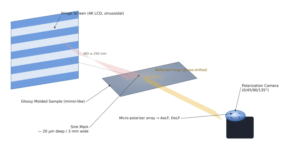
Phase measuring deflectometry (PMD)3 measures that change of direction directly. It treats the inspected face as a mirror, has the camera look at a fringe screen reflected in it, and works backward from how far the fringes have shifted to the slope of the surface. There is one thing I want to settle. To catch a 20 μm depth with a single camera, what has to be set and to what values, and what does polarization data actually add on top?
On a black mirror face, brighter light does not lift the dip
A dome light illuminates the whole inside of a hemisphere evenly and sends light in from every side. On a matte surface that even light is an advantage because it erases the shadows around a scratch, but on a near-mirror face the situation changes. The brightness that one point of a mirror-like face sends to the camera equals the brightness of the dome in the direction that point reflects, multiplied by the reflectance. If the inside of the dome is equally bright everywhere, the camera receives the same brightness whether the surface tilts 1° or 2°. Even the steepest part of this dip tilts only about 1.2°, so the more evenly the dome is built, the more cleanly the dip disappears from the image.
Fringe projection4, which throws stripes onto a surface to measure height, gets little traction here either. It reads how far the pattern formed on the surface slides sideways with height, but on a face dominated by specular reflection no pattern forms, and the projector lens just flashes back as a single bright spot. Even if a pattern did form, the numbers work against it. For comparison, take a triangulation angle of 30° and a fringe period of 2 mm on the surface: a 20 μm height then moves the phase by 0.036 rad, only 0.6 % of one period.
What this face gives back, in the end, is the direction in which light leaves it. The edge of the dip is a gentle slope, and a slope bends the reflected light sideways. To see where the bent light lands you need to know what is reflected in front of the surface, and deliberately making that something a patterned screen is where deflectometry starts. How far the pattern shifts is then read as which point of the screen, seen in the mirror, has entered each camera pixel.
How a 20 μm depth grows into 17 mm on the screen
The calculation assumes a resin refractive index of 1.5, 400 mm between the inspected face and the screen, and phase noise of 0.5 % of one period. If the cross-section of the dip is a smooth cosine curve, the steepest slope is π × depth ÷ width, or 20.9 mrad5. If it is a parabola with a crisp edge, it is 4 × depth ÷ width, or 26.7 mrad. A real sink mark sits somewhere between the two shapes depending on the mold and the resin, so I design with the smaller value, 20.9 mrad.
Light reflected from a mirror turns by twice the angle the face tilts. A slope of 20.9 mrad bends the reflected light by 41.9 mrad, which becomes a 16.8 mm shift on a screen 400 mm away. A depth of 20 μm shows up on the screen as a length about 840 times larger. Read with a 10 mm fringe period, that shift is 10.5 rad of phase, or 1.7 fringe periods, and about 290 times the 0.036 rad of the fringe projection case above.
The difference between height and slope becomes clearer when the same defect is drawn as two curves. The figure below puts height on top and slope underneath.
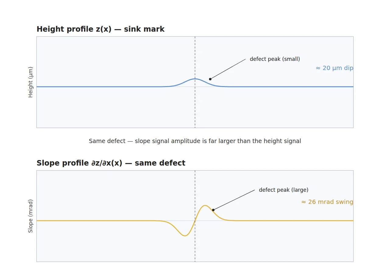
In the upper curve the defect is one small bend near the baseline, but in the lower curve it becomes a pair of peaks split up and down on either side of the center. The 26 mrad written in the figure assumes a cross-section with a crisp edge; with a smooth cross-section the peaks drop to around 21 mrad. The two peaks add up to zero area, and that property protects the slope signal later when the curvature component is filtered out. Against noise the margin is wide as well. Phase noise of 0.5 % is 0.05 mm on the screen, or 0.06 mrad of slope, so the dip signal is 335 times the noise.
That does not mean the decision threshold can come down near the noise. The shape variation of good parts sets the threshold more than the noise does, and before that, the fringes have to be recorded sharply by the camera for the 0.5 % phase noise assumption to hold at all.
The fringe period is set by the lens’s defocus
Since the screen pixels are a fine 0.18 mm, it sounds reasonable to display thin fringes for more precision. The camera, however, is focused on the inspected face, and the screen forms 400 mm farther away inside the mirror. With a 2/3-inch 5 MP polarization sensor (2,448 × 2,048 px, 3.45 μm pixels) covering a 200 mm field of view, the magnification is 0.042, and at F/5.6 the defocus blur6 on the screen plane is 0.042 × 400 ÷ (5.6 × 1.042), or 2.9 mm across. This value depends only on magnification, aperture and screen distance, whatever the focal length.
With a blur 2.9 mm across, a 3 mm fringe period keeps only 22 % of its contrast, 5 mm keeps 64 % and 10 mm keeps 90 %. My default is a 10 mm period, 55 screen pixels, where 90 % of the contrast survives. Stopping down to F/11 shrinks the blur to 1.5 mm but cuts the light to a quarter, and on a face with 4 % reflectance the exposure time grows by the same factor. The reason to choose a 4K screen lies in its large area more than in its fine pixels.
To cover a 200 × 167 mm field of view on a flat face through the mirror, the screen must be (lens-to-face distance + 400) ÷ (lens-to-face distance) times the size of the field of view. With a 25 mm lens the lens sits about 617 mm from the face, so 330 × 276 mm is needed, and a 31.5-inch 4K screen (697 × 392 mm) covers it with room to spare. Pull the WD7 in to 296 mm with a 12 mm lens and the required size grows to 470 × 393 mm, past the 392 mm height of the same screen. Swap lenses to shorten the WD and the screen runs short first.
The phase is read by phase shifting8. Shift the fringes four times by a quarter period and each pixel yields its phase along with the modulation9, which tells how sharply the fringes were reflected. A 10 mm period alone cannot tell which fringe is which, so a 400 mm period is captured as a second set and used for phase unwrapping10. Unwrapping stays steady only when the 2 mm position noise of the coarse period is smaller than a quarter of the fine period, 2.5 mm, and that holds as long as the ratio of the two periods stays under 50. Slopes in both directions need fringes in both directions, 16 frames in all, and if the screen refreshes at 60 Hz and each pattern waits two refreshes, capture alone takes 0.53 seconds. The part has to stay still for that time, and how it is stopped and held needs a separate review.
16.8mm
Shift that a 20.9 mrad slope makes on a screen 400 mm away
0.06mrad
Slope noise when phase noise is 0.5 % of a period (assumed)
2.9mm
Defocus blur on the screen plane at F/5.6
Put on one line, the three numbers show the character of this setup. The signal is generous and the noise is small, and what eats into the gap between them is blur and ambient light. The 50 lx ambient figure is only a starting point. Ambient light added evenly to all four shifted frames cancels out in the subtraction, but the noise and saturation it brings do not. The bigger problem is that the mirror face also reflects the ceiling lights beyond the screen. Places where light bends sharply, such as the edge of the dip, end up looking past the screen border, so I would write wrapping the screen in a black shroud on the same line as the lux figure.
One camera leaves an ambiguity of about 1 mrad per millimeter of depth
Single-camera deflectometry has one knot that does not come undone. A camera pixel only tells you that ‘this pixel is looking at that point on the screen’; it does not tell you at what depth along the camera ray the reflection happened. Assume a different depth and the normal that explains the same observation changes too. At an incidence angle of 30° and a screen distance of 400 mm, getting the depth wrong by 1 mm tilts the normal by 1.08 mrad.
Hold this number up against dip detection and the decision gets easier. If part placement is controlled within ±1 mm, the normal error is ±1.1 mrad, and even that is spread smoothly over the whole part, so it drops out at the step that filters the curvature component. Compute the smooth component with a Gaussian of 5 mm standard deviation and subtract it: near the dip that component reaches at most 0.3 mrad, so the 20.9 mrad slope peak survives almost intact. Apply the same filter to height and 20 μm shrinks to 17.6 μm. The pair of slope peaks has zero net area and barely mixes with the smooth component, which is why I start with one camera when the goal is detecting dips.
If the warp or curved shape of the part has to be measured in absolute terms, the story changes. A second constraint is then needed to pin down the depth, and the usual answers are a second camera and a reference plate that calibrates the geometry. The three patents in the table below each point to a different branch of that fork.
| Patent | Title | Assignee (original) | Priority · granted |
|---|---|---|---|
| US 11,092,432 B2 | Reference plate and method for calibrating and/or checking a deflectometry sensor system | Micro-Epsilon Messtechnik GmbH & Co. KG | 2016-10-24 · 2021-08-17 |
| US 10,731,972 B2 | Instantaneous phase mapping deflectometry | University of Arizona | 2016-11-18 · 2020-08-04 |
| US 10,228,331 B2 | Methods and apparatus for polarized wafer inspection | KLA Corp (KLA-Tencor Corp) | 2016-03-28 · 2019-03-12 |
Micro-Epsilon’s patent covers calibrating or checking the parameters of a deflectometry sensor system with a reflective plate carrying a predefined pattern and markings. I read it as a sign that the positions of the screen, the camera and the inspected face govern the result, enough that a single reference plate earned its own claims. According to its abstract, the University of Arizona patent multiplexes phase-shifted fringes by color into a single image and separates the X and Y directions with Fourier methods, so that moving objects in high-vibration environments can be measured too. KLA’s patent is a wafer inspection arrangement that chooses the illumination polarization, along with a rotatable waveplate and analyzer on the collection side, from defect and background scattering maps to raise the defect signal-to-noise ratio, using polarization for defect contrast more than for shape recovery.
Below 19° of incidence, polarization goes quiet
A polarization camera puts 0°, 45°, 90° and 135° polarizing filters on the four pixels of each group, one per pixel, and from a single exposure it gets the degree of linear polarization (DoLP)11, which shows how strongly the oscillation of the light leans to one side, along with its direction. For light reflected from smooth resin, the incidence angle sets the DoLP. At a refractive index of 1.5 it is 0.04 at 10°, 0.17 at 20° and 0.39 at 30°. A rule that sets the fusion weight to zero for pixels with DoLP below 0.15 is the same as discarding incidence angles under 18.9°, so a camera standing nearly perpendicular to the face leaves the polarization channel with nothing to do. Only a layout in which the camera sees the screen at 30° of incidence leaves a usable signal.
What the remaining signal adds can also be weighed in numbers. Near 30° of incidence the DoLP changes by 0.027 per degree, so with DoLP noise of 0.01 the zenith angle is known to 0.37°, or 6.5 mrad. That is 100 times coarser than the 0.06 mrad slope noise, so it does not help measure the slope of the dip. Used against the depth ambiguity, the relation of 1.08 mrad per millimeter narrows the depth only to a range of about 6 mm. My judgment is that polarization gives a rough starting point for the overall shape, and precise shape remains the job of a second camera or calibration.
When polarization is actually mixed in, the first obstacle is the screen. Most LCDs emit light that is already linearly polarized by the front polarizer, so the reflected light reaching the polarization camera mixes the polarization created by the surface with the polarization the screen started with. Either depolarize the screen light with a diffuser film, or measure the polarization direction of the screen and put it into the calculation. When the screen polarization leans hard to one side, some of the four pixel directions record almost dark, so it is safer to compute the phase on 2 × 2 groups that sum the four pixels. The pixel spacing then becomes 163 μm, and a 3 mm wide dip spans 18 of them.
Fortunately, no extra exposure is needed to see polarization. Averaging the four phase-shifted frames gives the same image as lighting the whole screen in an even gray, so the DoLP and its direction can be computed from the same 16 frames. Polarization signals swing widely with the resin type, surface coatings and contamination such as mold release agent, though, so the gain from this fusion cannot be guaranteed before a sample test.
Laying out the setup for one dip in a single table
Gathering the calculations into one table connects the minimum defect size, through the screen and lens, to the decision parameters in a single line. The table also notes that scratches are caught by a different route from dips. A width of 50 μm is narrower than one 81.7 μm pixel, so slope cannot resolve it, and it is more likely to show up as a drop in modulation where the fringes blur.
| Item | Value | Condition · basis | In plain words |
|---|---|---|---|
| ① Minimum defect size (μm) | Sink mark 20 μm deep · 3 mm wide, scratch 50 μm wide | Dip slope 20.9 mrad (cosine section, design value) to 26.7 mrad (parabolic section). The scratch covers 61 % of one 81.7 μm pixel | Dips are caught by their slope, scratches by blurred fringes |
| ② Lighting · screen | 31.5-inch 4K LCD (697 × 392 mm, 0.18 mm pixels), 400 mm from the face, fringe periods 10 mm · 400 mm | 90 % contrast at a 10 mm period with 2.9 mm defocus blur. Diffuser film to depolarize, black shroud around the screen, ambient light 50 lx or less | Match the fringe width to the lens blur |
| ② Camera · lens · WD | 2/3-inch 5 MP polarization sensor (2,448 × 2,048 px, 3.45 μm), 25 mm F/5.6, field of view 200 × 167 mm | WD of about 617 mm must be secured (thin-lens approximation), screen needed 330 × 276 mm, 30° incidence, depth of field12 about 45 mm | A shorter lens runs out of screen first |
| ③ Algorithm parameters | 4-step phase shift × 2 periods × horizontal · vertical = 16 frames, phase on 2 × 2 groups (163 μm) | Period ratio 40 (under 50). Slope residual above 5 mrad after subtracting a Gaussian of 5 mm standard deviation, connected region of 30 groups (0.8 mm²) or more. Fusion weight 0 for pixels with DoLP below 0.15 | The shape variation of good parts sets the threshold more than the 0.06 mrad noise |
What decides success in this table is whether the 617 mm WD and the 330 × 276 mm screen in row ② fit inside the actual equipment, more than the decision parameters. Deflectometry ties the screen, the inspected face and the camera into one optical path, so if a fixture or a light shield blocks even a little of that path, that area cannot be measured at all, and no algorithm parameter can fill the gap. The decision side has margin to spare. The ring of the dip where the slope exceeds 5 mrad covers about 6.0 mm², or 224 of the 2 × 2 groups, far above the 30-group criterion.
In some places another method simply does better. On faces dominated by diffuse reflection, such as matte paint or textured molding, the screen is not reflected, so fringe projection or photometric stereo, which shoots with the light coming from changing directions, is the right fit. If the measurement needs absolute height more than slope, I would look at confocal or interferometric methods to avoid the error that builds up when slope is integrated. Translucent resin mixes surface reflection with internal scattering and blurs the phase, so it needs a separate review. Which approach wins depends on the reflection properties of the actual part and cannot be guaranteed before a sample test.
Building the optics is the vision engineer’s job, but a few numbers in this table can be counted by molding and quality staff too. On the mold side, the slope changes directly as π × depth ÷ width whenever the depth or width of a sink mark changes; for the team bringing the machine in, the screen size and the WD set the size of the machine. This article explains technology and is not investment advice. See our Disclaimer.
Field Note
To bring up this setup, I would first map the slope of one good cover with no dip and see how many mrad the residual, after removing the curvature component, wanders across the part. If that wander exceeds half of the 5 mrad threshold, I would suspect part placement and the screen mounting before raising the threshold. With a reference sample carrying a 20 μm deep dip, I would check that the peaks come out around 20 mrad, and I would lift and replace the black shroud around the screen to find where ceiling lights are reflected.
Field Checkpoints
Once the residual and the peaks have been checked with a good cover and a reference sample, the items below are the last gate for the setup.
- Is a WD of about 617 mm from lens to face (25 mm lens, 200 mm field of view) actually available, clear of fixtures and light shields? (a distance measured inside the equipment in place of a drawing value)
- Is the screen large enough to cover the field of view seen in the mirror? (at least 330 × 276 mm with a 25 mm lens, larger for curved parts)
- Have the refractive index and specular share of the resin been checked? (whether the 1.5 assumption holds, and whether a large diffuse share keeps the screen from reflecting anywhere)
- Has the polarization direction of the screen light been measured, or depolarized with a diffuser film? (LCD light is usually already polarized one way)
- Is the fringe period set to 10 mm or more to match the 2.9 mm defocus blur? (thin fringes blur and lose their contrast)
- Is the curvature residual of good parts below half of the 5 mrad threshold? (shape variation sets the threshold more than the 0.06 mrad noise does)
- Is the screen wrapped in a black shroud so that ceiling lights are not reflected in the mirror face? (together with ambient light of 50 lx or less)
Frequently Asked Questions
Can the 16 frames be cut down by capturing the fringes in a single shot?
They can, at a price. Carry the phase-shifted fringes on separate color channels, as in the University of Arizona patent, and one image yields both horizontal and vertical phase, which helps in a vibrating environment. It needs a camera with color channels, though, and crosstalk between the channels has to be corrected separately. Stack color filters on top of a 2 × 2 polarizer array and the group that holds every color and every polarization direction grows larger, so the pixel spacing over a 200 mm field of view coarsens again. If the part can be held still for 0.53 seconds, I would choose to capture 16 frames in sequence with a monochrome polarization sensor.
Can a strongly curved cover be inspected with the same screen?
A convex surface fans the reflected light out, so the screen has to be much larger. Following two-dimensional rays for a 200 × 167 mm field of view and a 400 mm screen distance, a face curved along the width cannot be covered by a single 31.5-inch screen once its radius of curvature falls below about 520 mm, and a face curved along the height once it falls below about 1,210 mm. The height direction has less room because the 392 mm screen height is tight against the 167 mm field of view. Pulling the screen in to 200 mm lowers the limits to about 290 mm and 460 mm, but the slope signal also drops from 16.8 mm to 8.4 mm. To protect the signal, splitting the field of view into two shots works better.
Glossary
- [1] Sink mark sink mark
A shallow depression that forms on the surface of a molded part when thick sections shrink inward as they cool. On a glossy face it stands out only under glancing light. ↩ - [2] Specular reflection specular reflection
Reflection in which light bounces off in a single direction at the same angle it arrived, as from a mirror. Reflection that scatters in all directions is called diffuse reflection. ↩ - [3] Phase measuring deflectometry PMD
A method that reads the distortion of a fringe screen reflected in the inspected face as phase and derives the surface slope from it. It works on the same principle as judging the bends in a mirror by how warped a reflected window frame looks. ↩ - [4] Fringe projection structured light
A method that projects fringes onto a surface and measures height by triangulating how far the fringes slide sideways with height. Because the pattern has to form on the surface, it works best on matte faces. ↩ - [5] mrad milliradian
A unit of angle; 1 mrad is the angle that opens 1 mm at a distance of 1,000 mm. One degree is about 17.5 mrad. ↩ - [6] Defocus blur circle of confusion
The spreading of one point of an object in front of or behind the focused plane into a small disc in the image. The larger that disc, the sooner fine patterns are erased. ↩ - [7] WD working distance
The distance from the lens to the surface being inspected. The value in the text uses a thin-lens approximation measured from the lens center. ↩ - [8] Phase shifting phase shifting
A method that captures the fringes several times, shifted by a set step each time, and computes the phase from how the brightness of the same pixel changes. Ambient light added evenly drops out of this calculation. ↩ - [9] Modulation fringe modulation
How widely the brightness of a pixel swings across the phase-shifted images. Where light scatters, as at a scratch, the fringes blur and this value drops. ↩ - [10] Phase unwrapping phase unwrapping
The calculation that adds the period count to a phase folded between 0 and 2π, unfolding it into a continuous value. A coarse fringe period supplies that count. ↩ - [11] DoLP degree of linear polarization
A value from 0 to 1 that shows how strongly the oscillation direction of light leans to one side. For light reflected from a smooth dielectric face, it approaches 1 as the incidence angle grows, up to Brewster’s angle. ↩ - [12] Depth of field DOF
The front-to-back range that can be treated as in focus. The value in the text takes the permissible circle of confusion as two pixels (6.9 μm). ↩
References
- Micro-Epsilon Messtechnik GmbH & Co. KG, US patent US11092432B2, Reference plate and method for calibrating and/or checking a deflectometry sensor system (priority October 24, 2016; filed October 5, 2017; granted August 17, 2021)
- University of Arizona, US patent US10731972B2, Instantaneous phase mapping deflectometry (priority November 18, 2016; filed November 17, 2017; granted August 4, 2020)
- KLA Corp (original assignee KLA-Tencor Corp), US patent US10228331B2, Methods and apparatus for polarized wafer inspection (priority March 28, 2016; filed December 19, 2017; granted March 12, 2019)
- LUCID Vision Labs, Phoenix 5.0 MP Polarization Model (IMX250MZR/MYR) product specifications (2/3-inch, 2,448 × 2,048 px, 3.45 μm pixels, 0° · 45° · 90° · 135° polarizers)
- Formulas: peak slope of a cosine section = π × depth ÷ width, parabolic section = 4 × depth ÷ width, screen shift = screen distance × tan(2 × slope), slope noise = period × phase-noise fraction ÷ (2 × screen distance), normal-incidence reflectance = ((n − 1) ÷ (n + 1))², DoLP = (Rs − Rp) ÷ (Rs + Rp) (Fresnel equations), defocus blur on the screen plane = magnification × screen distance ÷ (F-number × (1 + magnification)), contrast under blur = 2J₁(πB/P) ÷ (πB/P), normal error = depth error × sin(2 × incidence angle) ÷ (2 × screen distance), depth of field ≈ 2 × F-number × permissible circle of confusion × (1 + magnification) ÷ magnification²
Related reading — Raising the Camera Leaves the Glint of Its Built-in Light in Place · How Strongly Cross-Polarization Suppresses Glare Depends on the Lighting Angle · How 3D Structured Light Measures a Solder Lead Lift That Brightness Cannot Show

Noctvision
An engineer who has handled mechanical design and project management for production equipment since 2005. Here I work through the cameras, lenses and lighting that go into equipment with formulas and public data, and record the assumptions and sources alongside the numbers.


You May Also Like
Coaxial Light Alone Does Not Settle Fine Scratches on Polished Metal
An 850 nm Band-Pass Filter Erases Factory Lights but Leaves Sunlight