Camera Interface Bandwidth Determines Resolution
INTERFACE
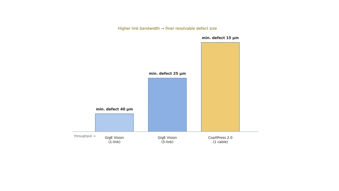
Covering the same area at the same speed, the smallest pixel size falls with the square root of bandwidth, and on 1GigE it stops at 12.7 μm.
Taking a 12 MP camera hunting 15 μm via cracks, I followed the bytes per second it needs, the limit of each link, the effect of bit depth and camera count, and what edge ROIs change.
About 13 min read
Around a via on a multilayer PCB, the exposed copper pad is a shiny surface, the solder mask outside it is semi-gloss, and the hole itself is a dark surface that returns almost no light. Copper reflects strongly in the specular1 way, so it stands bright under coaxial illumination2, and a 15 μm wide crack running from the pad toward the hole shows up as a thin dark line splitting that bright surface. Holding that line in 3 px takes 5 μm per pixel, which on a 4096 × 3000 px camera gives a field of view of 20.5 × 15.0 mm per frame.
Hang several of these cameras on one machine, and the cable shows its limit before the lens or the lighting does. When a camera produces more data than its link can carry, the frame rate has to drop, the resolution has to shrink, or only part of the image goes out, and all three end up cutting the pixels that see the crack. I tie the problem into one calculation: the smallest pixel size a link’s bandwidth allows when the same area is covered at the same speed.
Bytes per second for a 15 μm crack
The bandwidth needed is the product of pixel count, bytes per pixel and frame rate. Sending 4096 × 3000 px 8-bit mono images at 60 frames per second takes 12.29 MB × 60 = 737 MB/s. Packing the same camera at 10 bits raises that to 922 MB/s, and at 12 bits to 1,106 MB/s. Bit depth3 alone changes the bandwidth by up to 1.5 times. That is no small difference.
When a document puts this figure at 2.2 GB/s, it is worth checking whether it was calculated at 3 bytes per pixel, that is, 8-bit color in three channels, because 4096 × 3000 px at RGB 8-bit and 60 frames comes out at exactly 2.21 GB/s. Using the color figure for a mono inspection sizes the interface three times too large, and using the mono figure for a color camera leaves the link short. I write the pixel format on the first line of the spec before calculating bandwidth.
What each link can carry
On Ethernet-based GigE Vision, a 1 Gbps link has a raw rate of 125 MB/s, which is about 115 MB/s assuming 92 % efficiency after protocol overhead. Under the same assumption, 5GigE carries 575 MB/s and 10GigE 1,150 MB/s. CoaXPress 2.0 defined CXP-12, which puts 12.5 Gbps on one coaxial cable, and a Euresys article in Vision Systems Design dated March 28, 2017 says four CXP-12 connections transfer up to 50 Gbps, or 5 GB/s. That works out to 1.25 GB/s per cable, and the gap to 12.5 Gbps ÷ 8 = 1.56 GB/s can be read as the share used by line encoding4.
The results split. Sending full 12 MP 8-bit frames, 1GigE reaches 9.4 frames per second, 5GigE 46.8, 10GigE 93.6 and a single CXP-12 cable 101.7. Under the 60 fps condition, 1GigE and 5GigE fall short while 10GigE and CXP-12 have room to spare. The remaining difference is that CXP links camera and computer point to point and needs a dedicated frame grabber5, while the Ethernet side can use ordinary network gear and longer cable runs.
The formula by which bandwidth sets pixel size
What inspection actually demands is the area to sweep per second, more than a frame count. A line viewing a 20.5 × 15.0 mm field 60 times a second has an area rate6 of 18,450 mm²/s, and at 1 byte per pixel the pixel count needed is that area divided by the pixel area. Rearranged, the smallest pixel size is √(area rate × bytes per pixel ÷ bandwidth), so for the same area at the same speed, pixel size is inversely proportional to the square root of the bandwidth.
Plugging each link’s bandwidth into the formula gives 12.7 μm for 1GigE, 5.7 μm for 5GigE, 4.0 μm for 10GigE and 3.8 μm for a single CXP-12 cable. A 15 μm crack shrinks to 1.2 px on 1GigE, hard to read as a line, and to 2.6 px on 5GigE, just short of the 3 px mark. 10GigE and CXP-12 leave room below the 5 μm per pixel target, and the spare bandwidth can go to bit depth or frame rate.
737MB/s
Bandwidth to send 12 MP 8-bit mono at 60 fps
12.7μm
Smallest pixel for a 20.5 × 15.0 mm field at 60 fps on 1GigE (115 MB/s effective assumed)
1.25GB/s
Throughput of one CXP-12 cable (based on 5 GB/s for four)
Seen together, the three numbers make the interface the part that caps image quality. Even if the lens draws 5 μm, a link that allows only 12.7 μm means the crack forms on the sensor and still vanishes before it reaches the computer.
Bit depth and camera count eat the margin
With shiny copper and a dark via hole in the same field, 8 bits tend to saturate the bright side or bury the dark side, which makes 12 bits tempting for a wider dynamic range7. The bandwidth then becomes 1,106 MB/s, taking 96 % of 10GigE’s effective 1,150 MB/s and leaving almost no margin. On a single CXP-12 cable it is 88 %. Whether 8 bits are enough, as copper gloss and oxidation vary from lot to lot, cannot be guaranteed before a sample test.
Raise the count to six cameras and even at 8 bits a total of 4.42 GB/s flows into the computer. With CXP that takes six ports, one cable per camera; with 10GigE it takes six 10 Gbps ports plus host capacity to absorb the data. GigE Vision 3.0, released by A3 in a press release dated May 12, 2026, adds RoCEv2-based RDMA8 streaming that sends images from the camera into computer memory without passing through the operating system, lowering CPU use and latency. For a machine receiving many cameras over Ethernet, whether the cameras and network cards support it changes the host specification. The host can become the bottleneck too.
Cropping at the edge moves the bottleneck to recall
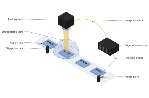
In place of more bandwidth, there is the path of sending less. The camera finds defect candidates first and sends only the regions of interest9 around them; with three 512 × 512 px regions per frame, that is 6.4 % of the original, or 47 MB/s at 60 fps, comfortable even on 1GigE. USI announced on September 8, 2026 an AI smart camera that combines an edge computing platform with AI vision software to run image analysis and inference in the camera, and TDK SensEI announced edgeRX Vision on July 15, 2025, handling up to 2,000 parts per minute and components as small as 1 mm by 0.5 mm.
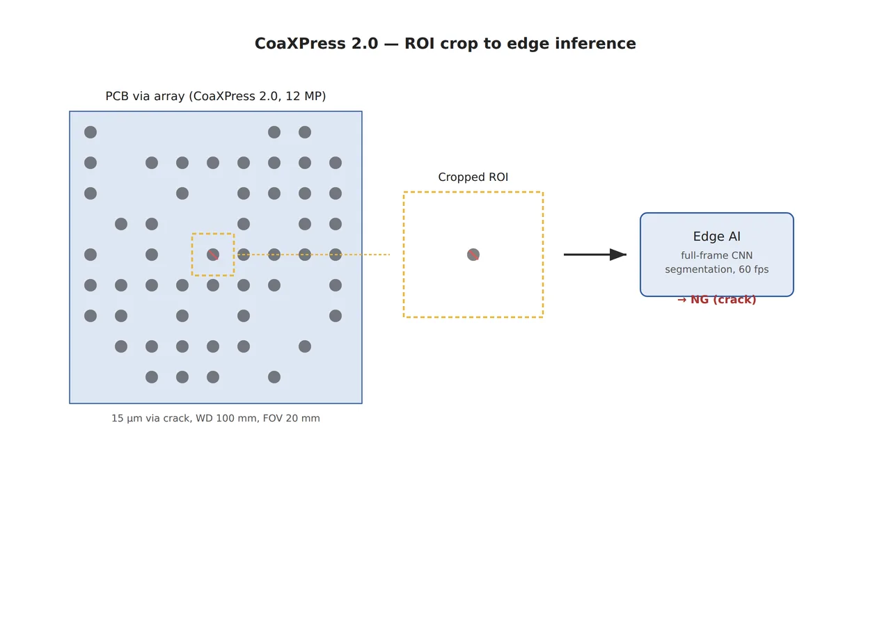
In a crop-and-send setup like the one in the figure, candidates the edge model misses never reach the computer at all. With edge recall10 at 99 %, 10 of every 1,000 defects get no chance to be seen by any later algorithm. The bottleneck has moved from the cable to the edge model’s recall. Even with cropping, I would send a share of full frames alongside to count separately the defects the edge model misses.
Not missing a 15 μm crack even on 1GigE
When setting up, write three things on one sheet: how many pixels the crack occupies, whether the link can carry those pixels, and how much bit depth and camera count eat into the margin. Taking 5 μm per pixel with a 4096 × 3000 px sensor of 3.45 μm pixels gives a magnification of 0.69×. A 35 mm lens puts the board about 86 mm from the principal plane of the lens by the thin-lens approximation and needs about 24 mm of extension beyond infinity focus, so a macro or telecentric lens matched to this magnification is worth considering too. The coaxial light’s mirror housing has to fit between lens and board, so the actual WD11 has to be checked on the datasheet.
| Item | ① Minimum defect size | ② Optical setup · lighting · WD | ③ Algorithm parameters |
|---|---|---|---|
| Resolving the crack | 15 μm wide = 3 px (5 μm/px) | 4096 × 3000 px, 3.45 μm pixels, 0.69× magnification, field of view 20.5 × 15.0 mm. Object distance about 86 mm with a 35 mm lens (thin-lens approximation; check the WD left after the coaxial housing on the datasheet) | 60 fps, 8-bit mono at 737 MB/s. Smallest pixel possible: 1GigE 12.7 μm, 5GigE 5.7 μm, 10GigE 4.0 μm, CXP-12 3.8 μm |
| Copper reflection · bit depth | A 15 μm dark line on copper | Coaxial illumination; measure the brightness gap between copper and via hole on samples | At 12 bits, 1,106 MB/s: 96 % of 10GigE, 88 % of CXP-12. Check first whether 8 bits are enough |
| Camera count · edge | 10 of 1,000 defects lost at 99 % edge recall | Six cameras total 4.42 GB/s: six CXP ports or six 10 Gbps ports | Three 512 × 512 px ROIs = 6.4 % of the original, 47 MB/s. Send some full frames too to count edge misses |
Lining the three rows up from top to bottom, the interface choice decides pixel size, bit depth and camera count all at once. If the pixel size set by the link exceeds a third of the crack width, no amount of work on the lens or algorithm below it brings the crack back.
There are also clear places where 1GigE is enough. On a line looking for defects over 100 μm, such as large voids or foreign matter on molded parts, with many cameras and long cable runs, the pixel size from the same formula fits within a third of the defect width and the simplicity of Ethernet wiring cuts cost. A structure that finishes the first decision at the edge and sends up only suspect frames also lowers the bandwidth needed considerably. Which side wins on total cost depends on defect size, surface reflectance and the real defect distribution, so it cannot be guaranteed before a sample test.
Converting bandwidth into pixel size is the number an engineer designing a multi-camera machine writes on the first page of the spec, and on the integration side it sets how many links and cards the system needs. When comparing camera quotes, it is quicker to check first whether the pixel format and per-link utilization are written down. This article explains technology and is not investment advice. See our Disclaimer.
Field Note
If six 12 MP cameras were going on one machine, my first step would be fixing the pixel format and calculating the bandwidth, before choosing a lens. With 737 MB/s for 8-bit mono at 60 fps as the baseline, a table of per-link utilization comes next, and if a sample measurement of the brightness gap between copper and via hole calls for 12 bits, that table gets rewritten. If CXP is on the table, the route and length the cables will actually take get checked on the drawing, and the speed guaranteed at that length gets matched against supplier data.
Field Checkpoints
Once the pixel format and the per-link utilization table are in, the questions below settle the interface.
- WD: does actual WD remain after fitting the coaxial light housing between lens and board? (object distance about 86 mm with a 35 mm lens)
- Is the pixel format (mono 8-bit, 12-bit packed, RGB and so on) on the first line of the spec before the bandwidth calculation?
- Has the smallest possible pixel size been calculated from each link’s effective bandwidth and compared with a third of the crack width?
- Has the need for 12 bits been checked from the brightness gap between copper and via hole?
- Can the host and the frame grabbers or network ports absorb the total bandwidth of all cameras?
- If edge ROI transfer is used, are edge misses counted separately with a share of full frames?
- Has the speed guaranteed at the actual CXP cable length been confirmed from supplier data?
Frequently Asked Questions
How do I choose between 10GigE and CoaXPress 2.0?
For one 12 MP 8-bit camera at 60 fps, both cope, so the remaining differences are wiring, cost and headroom for bit depth. If long cables and ordinary network gear matter most, 10GigE suits; if headroom for 12 bits or higher frame rates matters most, CXP-12 does. Effective bandwidth varies with the equipment combination, so measuring the actual setup beats the 92 % assumption.
Couldn’t compression make 1GigE work?
Lossless compression ratios swing with image content, so it takes a guarantee that even the worst frame stays within the link. Lossy compression can erase thin lines like a 15 μm crack first, which calls for caution in defect inspection. I would measure the compression ratio on the worst lot’s images and confirm that crack contrast survives compression before using it.
Is a line scan camera calculated the same way?
Yes. For line scan, pixel throughput is pixels per line times lines per second, and the board speed and pixel size set the lines per second. Feed that into the area-rate formula and the same conclusion follows: pixel size scales inversely with the square root of bandwidth.
Glossary
- [1] Specular reflection specular reflection
Reflection that leaves a smooth surface in one direction at the same angle the light came in. It is strong on copper pads. ↩ - [2] Coaxial illumination coaxial illumination
Lighting that turns light with a half mirror and sends it down along the lens axis. Flat reflective faces look bright and cracks look dark. ↩ - [3] Bit depth bit depth
How many bits represent one pixel’s brightness. 8 bits give 256 levels and 12 bits give 4,096. ↩ - [4] Line encoding line coding
Mixing extra bits into the data so the signal travels reliably. The real data rate ends up below the line rate by that share. ↩ - [5] Frame grabber frame grabber
An expansion card that receives camera images and hands them to computer memory. CoaXPress requires one. ↩ - [6] Area rate area rate
The area an inspection must sweep per second. It is the field-of-view area times the frame rate. ↩ - [7] Dynamic range dynamic range
The ratio between the brightest and darkest values one image can hold together. ↩ - [8] RDMA RDMA
Writing data received over the network straight into memory without passing through the operating system. CPU load and latency drop. ↩ - [9] Region of interest ROI
The part of an image the decision needs. Sending only that part cuts transmission. ↩ - [10] Recall recall, sensitivity
The share of real defects that the model catches as defects. ↩ - [11] WD working distance
The distance from the front of the lens to the inspected part. It decides whether the coaxial light housing fits in between. ↩
References
- Euresys (sponsored article, Vision Systems Design), “CoaXPress 2.0 | When CoaXPress comes with 12.5 Gbit/s (CXP12)”, 2017-03-28 (CXP-12 at 12.5 Gbps, four cables 50 Gbps = 5 GB/s). vision-systems.com
- Association for Advancing Automation (A3), “A3 Officially Releases GigE Vision 3.0, Opening New Possibilities in Machine Vision”, press release dated May 12, 2026. automate.org
- Plant Automation Technology, “USI Launches AI Smart Camera Solution to Accelerate Smart Manufacturing”, 2026-09-08. plantautomation-technology.com
- TDK SensEI, “TDK announces launch of TDK SensEI’s edgeRX Vision for detecting ultra-small customer product defects with AI”, 2025-07-15 (up to 2,000 parts per minute, components down to 1 mm by 0.5 mm). sensei.tdk.com
Related reading — When You Add Cameras to a Semiconductor or PCB Line, the Interface Rewrites the Optics · Why the PoE Network Card Sets the Limit on Your Optical Setup in a Multi-Camera Inspection Line · Edge AI Inference Latency Is Set by the Camera Interface Before the NPU

Noctvision
An engineer who has handled mechanical design and project management for production equipment since 2005. Here I work through the cameras, lenses and lighting that go into equipment with formulas and public data, and record the assumptions and sources alongside the numbers.


You May Also Like
Adding Reasons to an AOI Defect Call with a Vision Language Model
Why an Average Latency Inside the Deadline Is Not Safe