Why the PoE Network Card Sets the Limit on Your Optical Setup in a Multi-Camera Inspection Line
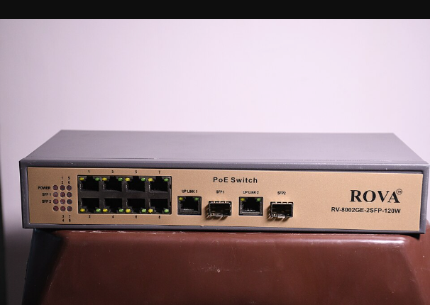
Scale a PCB inspection line from one camera up to four or eight, and the first problem the engineer runs into isn’t the lens — it’s cabling. As adoption of high-speed, high-resolution GigE Vision cameras spreads across advanced manufacturing processes, the supply of camera-dedicated PoE network cards is expanding right along with it. Delivering data and power over a single cable without separate power wiring is a clear advantage, but treating it as a mere power convenience comes back to bite you as false and missed detections at the line-setup stage. As camera count grows, the network card’s power budget and bandwidth run into a ceiling, leading to frame drops and timing error. The fix is to calculate the power and bandwidth budget alongside the lens and lighting spec at the very start of the design.
Why surface material and reflectivity need to be checked first
The first thing to address is the inspection target’s surface material and reflectivity. Solder mask, copper pads, and gold-plated connectors have widely different reflectivity, making it difficult for a single light to cover every region at once. A material with severe diffuse-reflection variation, like a gold-plated area, can have a highlight that looks like a defect, or a scratch that gets buried, from just a slight shift in lighting angle — and this is territory that cannot be confirmed before sample testing. On top of that, as PoE cable length grows, voltage drop increases power ripple on the camera, and combined with lighting-sync timing error, contrast starts to waver.
Camera count and power budget: the bottleneck isn’t the lens, it’s the network card
A power budget that was never a problem with one or two cameras becomes a bottleneck once you move to four or more cameras across multiple fields of view. A single network card’s total supply wattage is fixed, so once camera, lens-motor, and lighting-trigger power draw are added together, voltage on some ports can become unstable. In multi-camera inspection like semiconductor or display inspection, where the FOV is split narrower to secure resolution, camera count climbs accordingly, so a separate power-and-bandwidth allocation table needs to be drawn up at the very start of the design.
The algorithm is the last step for filling gaps left by optical and power infrastructure
Trying to solve this through algorithm tuning alone is risky. Software correction can somewhat ease lighting variation, but data with dropped frames or misaligned inter-camera synchronization is missing the original information entirely and cannot be reconstructed. It fits the proper order to treat algorithm parameters as the last step, cleaning up whatever variation remains after the optical and power infrastructure has been stabilized.
| Category | Item | Detailed spec |
|---|---|---|
| ① Minimum detectable defect size | PCB pattern micro-break/bridge | 20–50 µm (varies with pattern pitch, cannot be confirmed before sample testing) |
| ② Optical setup | Lens | Telecentric lens, 35–50 mm focal length, WD 100 mm secured |
| Lighting | Coaxial ring illumination (low angle), stabilized in the 3,000–5,000 lx range | |
| ③ Algorithm parameters | Synchronization | Inter-camera trigger-delay tolerance within ±2 ms |
| Network | Packet-loss threshold kept at 0.01% or below |
As the table shows, inspection precision hangs not only on the lens and lighting spec but simultaneously on infrastructure metrics — inter-camera synchronization delay and network packet-loss rate.
Field Checkpoints
- Has the reflectivity difference across the inspection target’s surfaces (solder mask, gold plating, copper pads, and the like) been distinguished in advance?
- Has WD (working distance) for the proposed lens-lighting combination been confirmed by actual measurement?
- Is the PoE network card’s power budget and bandwidth designed with margin for the total camera count?
- Has voltage drop from cable length and data integrity been re-confirmed under the actual wiring environment?


You May Also Like
Machine-Vision Inspection: Physics Comes Before Software
In the Age of 8K Line-Scan Cameras, the Lens Still Sets the Ceiling on Inspection Resolution