Keeping Frame Rate and Lighting from Colliding on a High-Speed Inspection Line
LIGHTING
Tighten the defect limit from 60 μm to 15 μm and, at the same speed, the frame rate rises 4 times and the light needed 8.3 times.
On a line where a 5 MP camera shoots boards passing at 1.1 m/s, I calculated the frame period, the strobe width, the amount of light and the transfer bandwidth in turn.
About 11 min read
On a line that fully inspects boards moving fast, such as PCBs or display panels, tightening the defect limit never changes just one camera setting. Seeing smaller defects means shrinking the area each pixel covers, which narrows the field of one frame, so the camera has to shoot more often at the same speed. Raising the frame rate1 cuts the light and time available per frame, and if that calculation is skipped, inspection runs on dark, smeared images while fine scratches and particles flow through to shipment. The surface comes before the calculation. Matte solder mask scatters light fairly evenly, but gold-plated pads or glass panels reflect in one direction like a mirror, so under the same lighting their brightness differs several times over. On boards that mix strongly reflective materials the result flips with the lighting angle, so the numbers below assume a near-matte surface, and results on glossy materials cannot be guaranteed before a sample test.
Here is the assumed setup. A 5 MP global shutter2 camera with 2,448 × 2,048 px and 3.45 μm pixels has its 2,048 px along the direction of travel, the boards pass at 1.1 m/s, and consecutive frames overlap by 10 % of the field. The current setup sees a 60 μm defect over 3 pixels at 20 μm per pixel, and the calculation covers a product change that requires seeing a 15 μm defect over the same 3 pixels. The control of the conveying mechanism that moves the boards needs a separate review, but the speed value is used as an input to the calculation.
Quadruple resolution, quadruple frames at the same speed
At 20 μm per pixel the field along the direction of travel is 2,048 × 20 μm = 41.0 mm, and with 10 % overlap one frame is taken every 36.9 mm of board travel. At 1.1 m/s that is 29.8 frames per second. Seeing a 15 μm defect over 3 pixels takes 5 μm per pixel, so the field shrinks to 10.2 mm, and a frame is needed every 9.2 mm, which makes 119.4 frames per second. Cutting the defect limit to a quarter raised the frame rate exactly fourfold.
The lens changes too. The magnification3, pixel size divided by pixel coverage, grows from 0.17 to 0.69, and a board seen from about 170 mm through a 25 mm lens now has to be seen from about 122 mm through a 50 mm lens. As the WD4 between lens and board shrinks by 47 mm, the room for the light shrinks with it, and even at the same f/5.6 the depth of field5 goes from 3.05 mm to 0.27 mm. The setup now loses focus if the board warps even slightly, so at this point I go back and check the board warpage spec first.
Each frame gets only 8.38 ms
At 119.4 frames per second one frame period is 8.38 ms. Exposure, readout and transfer all have to finish inside it, and the inspection computer has to process each frame within 8.38 ms or run a pipeline6 that overlaps several frames. At 29.8 frames it was 33.5 ms, so the same algorithm now has to finish in a quarter of the time. The time budget runs out first. Whether the camera can overlap exposure and readout is checked under the trigger7 mode section of its spec sheet.
The transfer volume grows as well. Sending 8-bit 5 MP images at 29.8 frames per second takes 149.6 MB/s, or 1.20 Gbps in bits, already above the 1 Gbps theoretical limit of a single Gigabit Ethernet link. At 119.4 frames it becomes 598.4 MB/s, 4.79 Gbps, which calls for an interface such as 10 Gigabit Ethernet or CXP-12 of CoaXPress 2.0, whose single connection runs at 12.5 Gbps. How to match the bandwidth8 and what it costs is calculated separately in the camera interface bandwidth article.
Light comes up eight times short
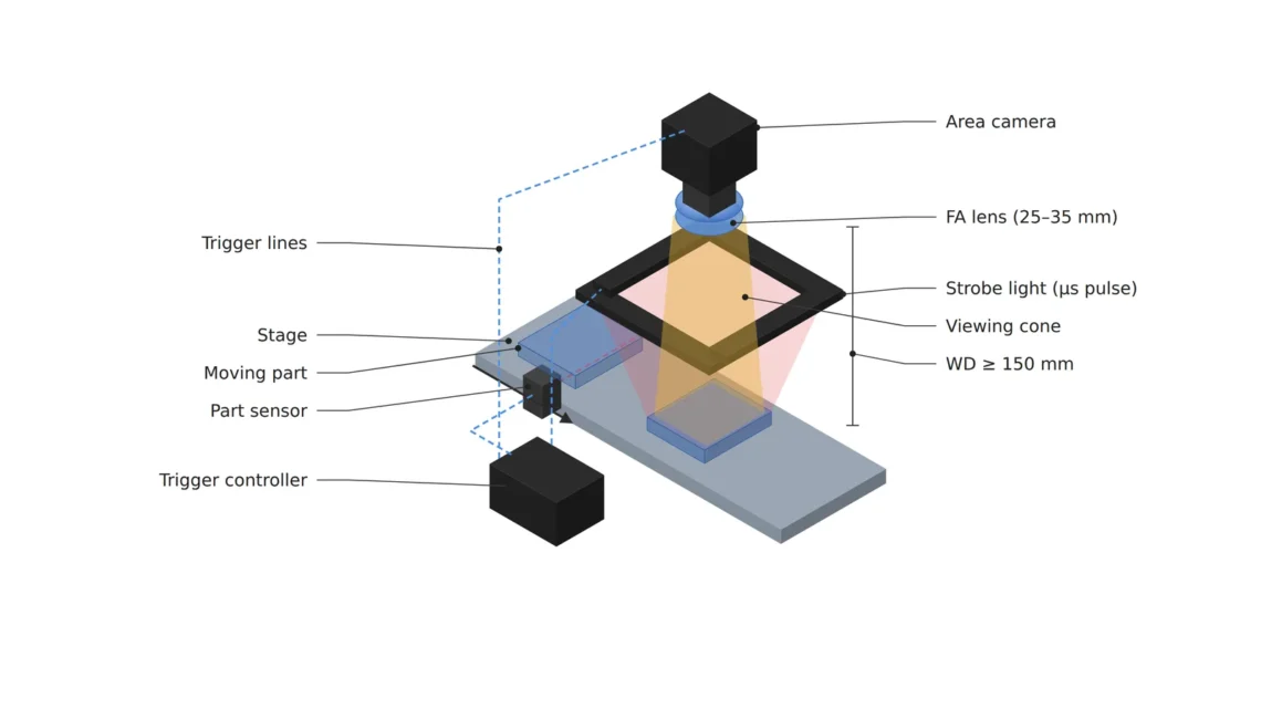
When shooting a moving board, the sharpness of a frame is set by how long the light comes in. If the board moves more than one pixel during that time, defect edges smear along the direction of travel, so the light-on time has to be shorter than the pixel coverage divided by the speed. At 20 μm per pixel that is 20 μm ÷ 1.1 m/s = 18.2 μs, and at 5 μm per pixel 4.55 μs. A light that fires strongly for only that short time is a strobe9, and even with a longer camera exposure window, the time the image forms is set by the strobe width.
The light one pixel receives is proportional to the light-on time and, at the same aperture, falls in inverse proportion to (1 + magnification)² as magnification grows. The on-time drops to a quarter and a further factor of (1 + 0.17)² ÷ (1 + 0.69)² = 0.48 applies, so each pixel receives 0.120 times the light. Getting an image of the same brightness takes light 8.3 times brighter, 3.05 stops. Opening the aperture three stops to make it up would cut the 0.27 mm depth of field to a little over a third again, so I take this share from the instantaneous brightness of the strobe instead of the aperture.
Raise the frame rate 4 times
and it seems the light only needs to be 4 times brighter.
Calculated for the 15 μm setup
the light-on time drops to a quarter and a 0.48 magnification loss comes on top, so at the same aperture the light has to be 8.3 times brighter.
The average heat is smaller than one might fear. Firing a 4.55 μs strobe 119.4 times a second gives a duty cycle10, the share of time the light is on, of 0.054 %. Making a continuous light 8.3 times brighter raises its heat 8.3 times as well, but short pulses have low average power, which leaves room to drive the current above the rating for an instant. The limit then comes from the peak current the LED and driver can take and how fast the current rises, more than from average heat, and those conditions are covered in the strobe overdrive article.
A strobe outside the exposure window loses light and edges together
On a trigger signal the camera opens its exposure window after a set delay, and the strobe waits its own delay from the same signal before firing. If the two delays drift apart, part of the pulse fires outside the exposure window, and light outside the window leaves nothing in the image. With the exposure window set to 10 μs and a 4.5 μs pulse running 2 μs past the end of the window, 44 % of the light is lost. That is close to half.
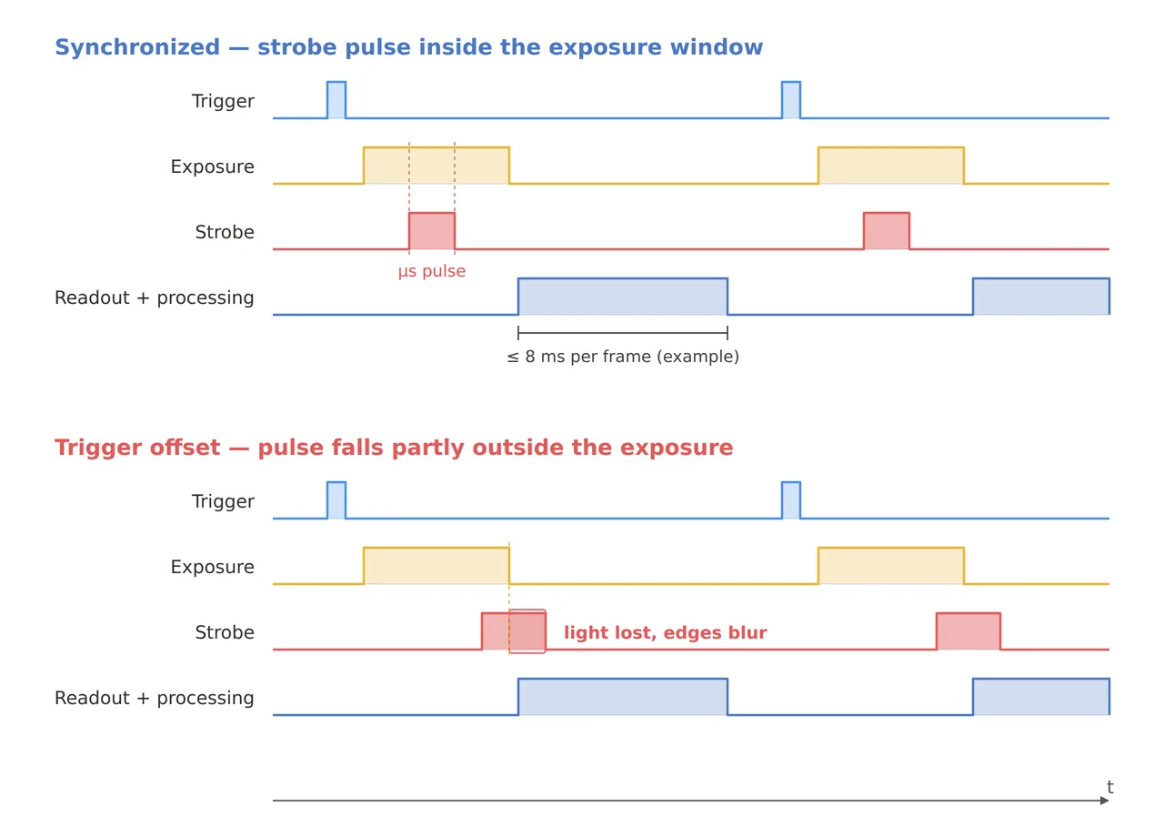
On the inspection side this loss shows up as defects that suddenly fade. With the pulse straddling the edge of the window, each trigger clips a slightly different share, frame brightness wobbles, and small defects near the threshold get caught in some frames and missed in others. So I open the exposure window generously wider than the pulse and set the two delays so the pulse lands in the middle of the window. Widening the window does not add smear, since the time the image forms is set by the pulse width, and only the share of ambient light leaking in grows slightly.
Three setups side by side at 30, 119 and 60 fps
The table puts three setups on the same camera side by side, changing only the defect limit and the speed. The last row halves the board speed; changing the speed itself is a matter for the conveying side, so only the numbers are compared here.
| Setup | ① Minimum defect size | ② Optical setup · WD | ③ Algorithm parameters · time budget |
|---|---|---|---|
| Current (1.1 m/s, 29.8 fps) | 60 μm = 3 px (20 μm/px) | 25 mm lens, WD about 170 mm from the principal plane, f/5.6 depth of field 3.05 mm, strobe 18.2 μs or less | 33.5 ms per frame, 1.20 Gbps transfer (8-bit), inspection within 33 ms |
| 15 μm limit (1.1 m/s, 119.4 fps) | 15 μm = 3 px (5 μm/px) | 50 mm lens, WD about 122 mm, depth of field 0.27 mm, strobe 4.55 μs or less, 8.3 times the light at the same aperture | 8.38 ms per frame, 4.79 Gbps transfer, inspection within 8 ms or pipelined |
| 15 μm limit, half speed (0.55 m/s, 59.7 fps) | 15 μm = 3 px (5 μm/px) | 50 mm lens, WD about 122 mm, strobe 9.09 μs or less, 4.2 times the light | 16.8 ms per frame, 2.39 Gbps transfer, inspection within 16 ms |
Comparing the three rows shows that the cost of tightening the defect limit piles up on light and time more than on the camera. The second row works on the same camera but needs 8.3 times the strobe brightness, 4.79 Gbps of transfer and 8 ms inspection all reset, while the third row gives up speed and halves the load on light and bandwidth. The opposite approach has its conditions too: at a station where the board stops, continuous light and a long exposure are enough without a strobe, and if defects occur in only a few places, looking at just those spots at high magnification uses fewer frames.
Numbers to settle before speeding up
When someone proposes raising the frame rate, I write down four numbers first: the frame period, the upper limit of the strobe width, the light multiple including magnification, and the transfer bandwidth. In this example they are 8.38 ms, 4.55 μs, 8.3 times and 4.79 Gbps, and if the current equipment cannot meet even one of them, swapping only the camera will not get the line running. With all four written on one line, the people responsible for lighting, cameras and inspection software talk about the same numbers.
The people who draw these numbers as one timing diagram are the vision engineers of high-speed lines, and for beginners I recommend starting by drawing the frame period and the pulse width split into microseconds. From the investment side, tightening the defect limit means changing the lighting, the interface and the inspection computer together, more than swapping a camera, so the quote grows to three line items. This article explains technology and is not investment advice. See our Disclaimer.
Field Note
If I bring up a setup for the new defect limit, I keep the board still, shoot the same spot while pushing the strobe delay in 1 μs steps, and mark the two points where brightness starts to fall as the two ends of the exposure window. I place the 4.55 μs pulse in the middle of those two ends, run the board at 1.1 m/s and watch whether defect edges stay within one pixel. If an edge spreads past one pixel, I check the trigger signal jitter on an oscilloscope before shortening the pulse any further.
Field Checkpoints
To move the timing and light numbers into the spec sheet, answer the questions below one at a time.
- Is there height left for the strobe light inside the roughly 122 mm WD of the 50 mm lens? (47 mm less room than with the 25 mm lens)
- Do exposure, readout, transfer and inspection finish within the 8.38 ms frame period, or overlap in a pipeline? (a single late frame means a dropped frame)
- Is the strobe width at or below 4.55 μs, the pixel coverage divided by the speed? (longer than that and defect edges smear past one pixel)
- Have the two delays been set so the strobe pulse sits in the middle of the exposure window? (light outside the window leaves nothing in the image)
- Have you chosen an interface and receiver that handle 4.79 Gbps of transfer? (a single Gigabit Ethernet link carries 1 Gbps)
- Have you checked the brightness of strongly reflective materials such as gold-plated pads or glass on sample boards? (the calculation assumes a near-matte surface)
Frequently Asked Questions
Can I just make a continuous light brighter?
With the exposure cut to 4.55 μs, making a continuous light 8.3 times brighter raises its heat 8.3 times too, and that heat wears down both the lifetime and the brightness stability of the light. A strobe delivers the same instantaneous brightness at a duty cycle of only 0.054 %, so its average heat is far lower. Where the exposure can stay long, as at a station where the board stops, a continuous light is the simpler choice.
Does the same calculation work with a rolling shutter camera?
A rolling shutter starts the exposure of each image row at a different time, so a moving board comes out skewed. Firing the strobe only during the short interval when all rows are open at once avoids that problem, but creating that interval stretches the exposure and lowers the frame rate. The size of the skew during motion is calculated in the rolling shutter skew article.
Glossary
- [1] Frame rate frame rate, fps
The number of images a camera takes per second. At 119.4 frames per second one frame period is 8.38 ms. ↩ - [2] Global shutter global shutter
A readout in which every pixel starts and ends its exposure at the same moment, so moving objects are not skewed. ↩ - [3] Magnification magnification
The size of the image on the sensor divided by the size of the object. When a 3.45 μm pixel covers 5 μm on the object, the magnification is 0.69. ↩ - [4] WD working distance
The distance from the lens to the surface being inspected. The values here use a thin-lens approximation from the lens principal plane; the distance from the lens front comes from the lens drawing. ↩ - [5] Depth of field depth of field, DOF
The depth range in front of and behind the focus distance that still looks sharp. The values here assume a circle of confusion of two pixels (6.9 μm). ↩ - [6] Pipeline pipeline
Processing that starts on the next frame before the current one is finished, overlapping several frames in stages. ↩ - [7] Trigger trigger
The electrical signal that tells the camera and the light when to capture. It comes from a sensor or encoder that reads the board position. ↩ - [8] Bandwidth bandwidth
The amount of data an interface can carry per second. It is written in bits (Gbps); dividing by 8 gives bytes. ↩ - [9] Strobe strobe
A light that switches on strongly for only a brief moment. It takes over the job of the shutter when freezing a moving object. ↩ - [10] Duty cycle duty cycle
The share of total time the light is on. Firing 4.55 μs pulses 119.4 times a second gives 0.054 %. ↩
References
- Vision Systems Design (contributed by Euresys), CoaXPress 2.0 | When CoaXPress comes with 12.5 Gbit/s (CXP12) (CXP-12 at 12.5 Gbps per connection, 50 Gbps over four)
- Formulas: field along travel = pixel count × pixel coverage, frame rate = speed ÷ (field × 0.9), strobe width limit = pixel coverage ÷ speed, magnification m = pixel ÷ pixel coverage, light per pixel ∝ on-time ÷ (N² × (1 + m)²), transfer = width × height × bit depth × frame rate, object distance = f × (1 + 1/m), depth of field ≈ 2 × N × c × (m + 1) ÷ m², duty cycle = pulse width × frame rate
- Assumptions: 5 MP global shutter camera (2,448 × 2,048 px, 3.45 μm pixels), 8-bit output, 2,048 px along travel, 10 % overlap between frames, board speed 1.1 m/s, defects at 3 pixels, f/5.6
Related reading — What Optical Design Needs to Not Miss Defects on a High-Speed Line · Catching the Moment Frames Miss with an Event Camera · Moving Parts Are Frozen by How Long the Light Stays On

Noctvision
An engineer who has handled mechanical design and project management for production equipment since 2005. Here I work through the cameras, lenses and lighting that go into equipment with formulas and public data, and record the assumptions and sources alongside the numbers.


You May Also Like
Why Are the Ends of a Line Scan Image Dark?
In SWIR, One Stop Down Erases a 3.4 μm Pixel