Parts at Every Height, One Focus Plane — Can It All Stay Sharp? Liquid-Lens EDOF and the Division of Labor with Interface Bandwidth
Introduction — Why Everything in One Frame Has to Be Sharp
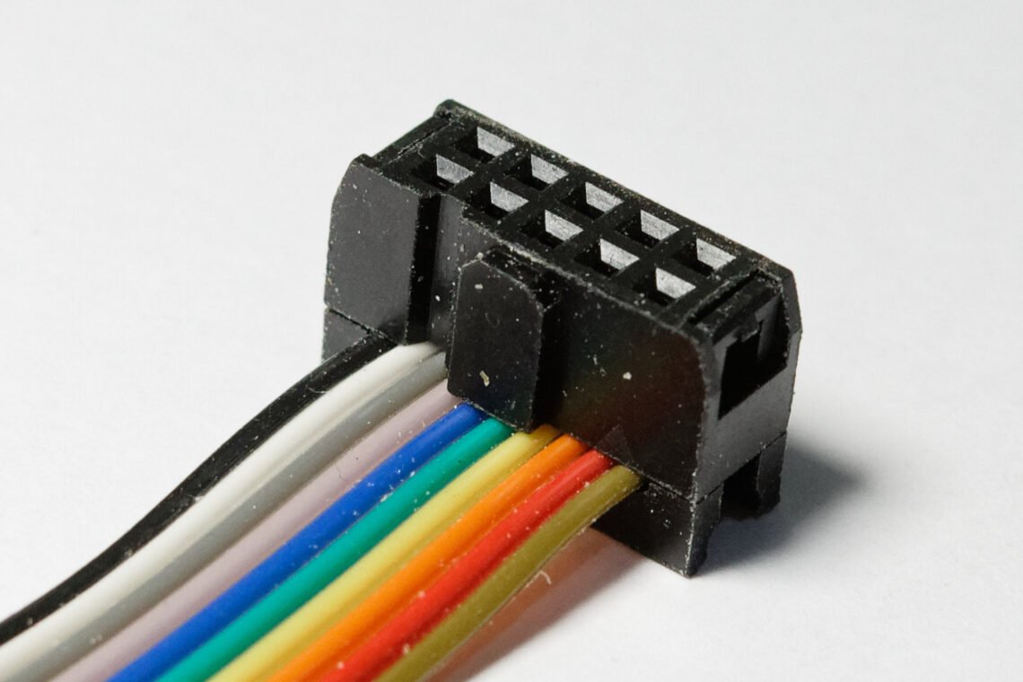
Inspecting multi-pin connector housings, you run into this often: the insertion depth of the pins in frame varies by 0.3–0.5 mm lot to lot, sometimes even within the same part. Cover the whole field of view with a single fixed-focus lens and the near pin tips come out sharp while the far pin tips blur — and in that blurred region, the boundary of a micro-crack or burr defect disappears entirely, leading straight to a missed detection. Run the line with this left unaddressed and defects leak through as contact failures at downstream or final-assembly stages, at a cost far higher than catching them at the initial inspection stage. Go the other way and stop the aperture down too far to avoid the depth shortfall, and diffraction drags overall contrast down, landing you in the opposite dilemma of rising false detections.
The solution is to design three layers together: the optical hardware, the algorithm, and the transmission interface that connects them. A liquid lens shifts the focal plane on a millisecond timescale to capture multi-focus frames, a deep-learning-based deblur/fusion algorithm builds a single extended-depth-of-field (EDOF) image from them, and an interface that can transmit the increased frame count without delay ties the whole thing together.
Body — Three Layers Connecting Focus, Fusion, and Transmission
The target’s surface material and reflectivity have to be defined first. Multi-pin connector pins are almost always tin-plated or gold-plated, giving them a strongly specular metal surface. On a surface like this, even when focus is correct, if a highlight-saturated region overlaps a defect boundary, the judgment can waver — so reflectivity variation across plating lots needs to be measured before designing the EDOF setup. On lots with heavy gloss variation, whether the same EDOF parameters apply across every lot cannot be confirmed before sample testing.
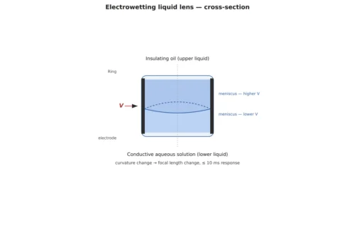
Point: It’s more advantageous, for both inspection speed and durability, to handle focal-plane movement with an electrowetting liquid lens rather than a mechanical drive. Reason: A liquid lens changes refractive power by using voltage to deform the interface between two liquids, so there’s no mechanical wear, and focus switching finishes on a millisecond timescale, keeping its impact on inspection takt time small. Example: A recently published EDOF technique combining a liquid lens with Deblur-UNet sequentially captures multi-focus frames and then performs deblurring and fusion simultaneously via deep learning, producing a single fully sharp image across the whole field without any separate mechanical scanning stage. Point: In the end, simply changing the lens-drive method resolves half of the depth-of-field problem at the hardware layer.
Point: That said, liquid-lens EDOF results depend heavily on the quality of the frame-fusion algorithm, so the optical setup alone cannot guarantee the detection rate. Reason: Simply averaging multi-focus frames, or selecting pixels by sharpness alone, produces artifacts at focus-transition boundaries, leaving boundary afterimages where non-defective areas can look like defects. Example: Deblur-UNet-family fusion models are being designed to suppress boundary artifacts by combining per-frame sharpness maps through learned weighting, and this approach favors preserving defect shape without boundary distortion even down to 20 µm-class micro-cracks. Point: In other words, liquid-lens EDOF is a technique that’s only complete when optics and algorithm are bundled together as one set.
Point: As the number of multi-focus frames increases, the transmission bandwidth between camera and frame grabber becomes a new bottleneck. Reason: Producing one EDOF image requires sequentially capturing multiple frames, and conventional Camera Link (up to roughly 2.8 Gbps) struggles to transmit that many frames from a high-resolution sensor within takt time. Example: CoaXPress currently supports up to 12.5 Gbps per channel (CXP-12), and CoaXPress v3.0, currently in development, targets up to 25 Gbps per link along with unifying fiber-optic cable specs — enough to support the bandwidth demands of multi-focus EDOF or of a camera like the Teledyne e2v Perciva 5D that pulls 2D and 3D data simultaneously. Point: Once the focus problem is solved, the next thing to check is whether the interface can stream the increased data volume in real time.
When a Fixed-Focus Telecentric Lens Beats Liquid-Lens EDOF
Liquid-lens EDOF isn’t the answer to every height-variation problem. On a line with low depth requirements, where insertion-depth variation already falls within the lens’s native depth-of-field range, it can be more advantageous — in terms of processing latency and system complexity — to skip multi-focus capture and fusion computation altogether and simply secure depth by stopping down a fixed-focus telecentric lens appropriately. This is especially true on high-speed lines with very short takt time and almost no per-frame processing margin, where the computational load of multi-focus fusion can itself become the bottleneck. That said, this judgment depends on the part’s height-variation range, required depth, and lot-to-lot reflectivity variation, so which side is actually favorable cannot be confirmed before sample testing.
Core Skeleton Matching Table
| Item | Detail |
|---|---|
| ① Minimum defect size to detect | 20 µm (pin-tip micro-crack/burr baseline) |
| ② Optical setup | Lighting: coaxial epi-illumination + diffuse dome combined, illuminance approx. 3,000 lx / Lens: electrowetting liquid-lens module (variable focus) + auxiliary fixed-focus lens, 25 mm focal length / WD 90 mm secured (covering a 0.5 mm pin-height variation range) |
| ③ Algorithm parameters | Multi-focus capture of 5–7 frames, Deblur-UNet-based sharpness-weighted fusion, fusion window 3×3 px, transmission bandwidth of CoaXPress CXP-12 (12.5 Gbps per channel) or higher |
Implication: What this table shows at its core is that none of the three items exists independently. The smaller the minimum defect size, the higher the required resolution and multi-focus frame count climb, and transmission-bandwidth requirements rise right along with them. Select the lens and interface before pinning down WD, and you’re likely to end up redesigning the whole setup later once the depth range turns out insufficient.
Field Checkpoints
- Has the WD (working distance) been measured in advance to confirm it sufficiently covers the part’s maximum height variation, including pin insertion-depth variation?
- Has reflectivity variation been measured across plating lots, so EDOF parameters are designed as lot-adaptive rather than fixed values?
- Has the transmission bandwidth resulting from the increased multi-focus frame count been calculated against the current interface’s (Camera Link/GigE/CoaXPress) limits on a takt-time basis?
- Has it been pre-verified with a sample set that the fusion algorithm’s focus-transition boundary artifacts aren’t confused with actual defects?
This post was produced through Noctvision’s automated research/drafting pipeline. Figures and setup parameters are general reference values; actual application must go through sample testing on the target part.


You May Also Like
Liquid Lens Autofocus: Solving the Focus Problem on High-Mix, Low-Volume Production Lines
The Line-Scan Camera You Picked by Line Rate Alone — Why It Still Misses Defects: TDI and the Resolution Design Relationship