The Camera Cannot Be Bolted On Last — Reserving Space and WD for Vision Cameras and Lighting at the Mechanical Design Stage
OPTICS / LIGHTING
When you try to fit a vision station into the “leftover space” after the machine’s mechanical design is finished, the camera usually fits but the lighting does not. A low-angle ring light has to come down close to the part, a dome light needs a diameter much larger than the part, and a coaxial light box takes up height in front of the lens.
When space runs short, the WD gets reduced, and a WD change cascades into magnification, FOV and resolution. Changing the lens misaligns the lighting position again, and in the end brackets, fixtures and covers are remade or the lighting method is compromised. Compromised lighting loses contrast, and that loss cannot be fully recovered by the algorithm.
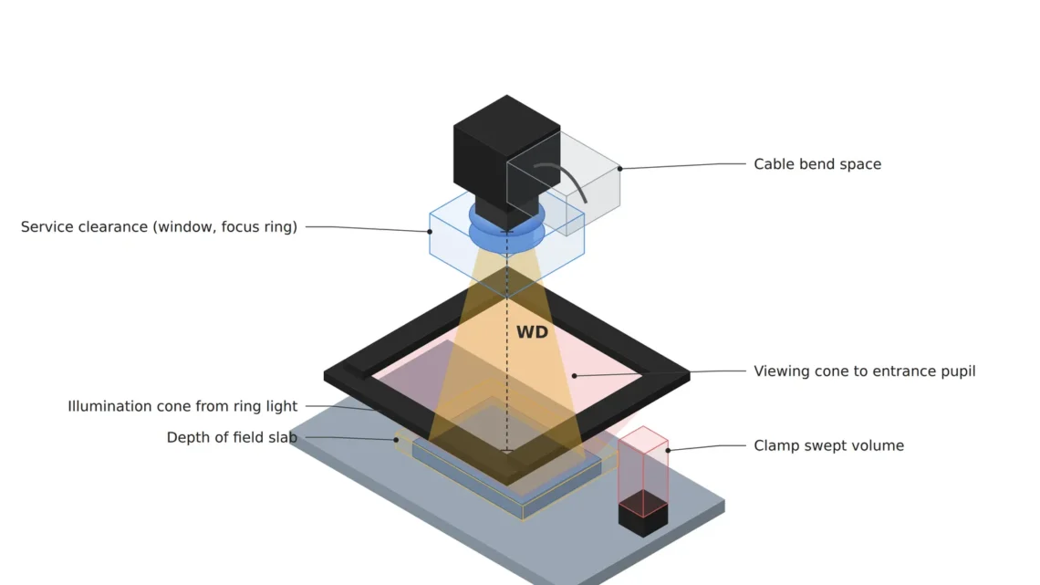
The fix is to design the vision station first as “space” rather than as “parts”. Model the viewing cone, illumination cone, depth-of-field slab and service clearance in 3D CAD first as transparent virtual bodies — optical keep-out volumes — and run interference checks so mechanical parts do not invade them. This article lays out the formulas that size those spaces and the modeling order.
The first drawing of a vision station should be not the camera’s shape but the space the light travels through.
1. The Four Volumes That Make Up the Optical Keep-Out Space
Point. The space a vision station occupies is not the outline of the camera and lens but the four volumes the light travels through.
Reason. (1) The viewing cone — the volume of imaging rays from the part’s FOV to the lens entrance pupil; (2) the illumination cone — the volume the incident light passes from the source to the part; (3) the depth-of-field slab — the focus tolerance thickness that holds the part height variation; (4) the service clearance — space for cleaning the protective window, turning the focus ring, and the cable connector and its bend radius. If any one of them is blocked by a mechanical part, it shows up as vignetting, shadows or defocus.
Example. In a station that inspects injection-molded connector housings on a fixture, the moment a clamp lever enters the illumination cone while it moves, a shadow appears only on that edge and causes over-detection. The trap is that the static assembly drawing shows no interference. Moving parts must be checked against the keep-out space over their whole motion path.
Point. Once the four volumes exist as transparent CAD bodies, mechanical designers can protect vision performance with interference checks alone, without optical calculations.
2. Width of the Viewing Cone — Calculate Whether a Light’s Aperture Blocks the View
Point. A light placed between the lens and the part, such as a ring light or a coaxial box, needs an aperture larger than the width of the viewing cone at that height.
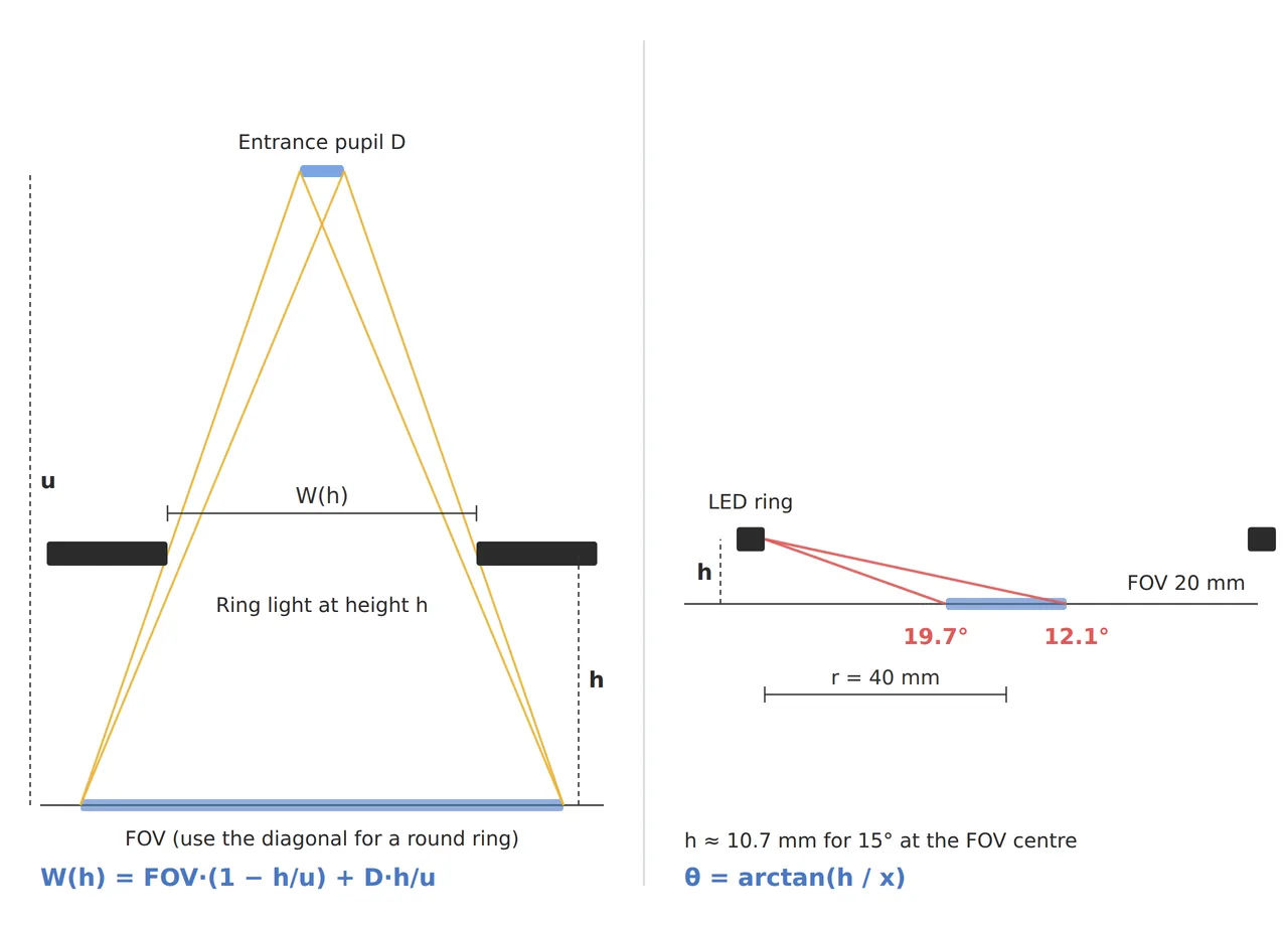
Reason. With an ordinary (entocentric) lens, rays from the edges of the FOV converge toward the lens entrance pupil. Adding up, for both ends of the FOV, the width the ray bundle from an edge point occupies at height h above the part, the aperture width needed to pass without vignetting is W(h) = FOV × (1 − h/u) + D × h/u (u: object distance to the entrance pupil, D: entrance pupil diameter). For a round aperture, use the FOV diagonal, not the FOV width, so that all four corners survive. With an object-side telecentric lens the chief rays are parallel and the width does not shrink with height, so the aperture must be larger than the FOV.
Example. Take a FOV of 100 mm × 73.2 mm (the 4096 × 3000 px aspect ratio), an object distance of 202 mm, and a 25 mm F4 lens (entrance pupil diameter approximated as 25 ÷ 4 = 6.25 mm), with a ring light placed 30 mm above the part. Using the FOV diagonal of about 123.95 mm gives W = 123.95 × (1 − 30/202) + 6.25 × 30/202 ≈ 106.5 mm. Choosing a 100 mm inner-diameter ring by looking only at the 100 mm width can therefore block the four corners.
Point. Compare a lighting catalog’s inner diameter not with the FOV width but with a value calculated from the FOV diagonal, the mounting height and the entrance pupil together. The actual position and diameter of the entrance pupil differ with each lens design, so confirm the final value with the lens data.
3. Low-Angle Lighting and Mounting Height — The Incidence Angle Sets the Space
Point. For dark-field and low-angle lighting, the desired incidence angle directly sets the mounting height of the light, so it must be placed first in the mechanical design.
Reason. If a ring light is at height h above the part surface and the horizontal distance between a point on the source and the point where the light lands on the part is x, the incidence elevation angle is θ = arctan(h / x). At the FOV center x is the ring radius r, but from the same source the near edge of the FOV is at x = r − FOV/2 and the far edge at x = r + FOV/2, so the angle is a range inside the FOV rather than one value. The lower the angle, the closer the source comes to the part, and the sooner it collides with fixtures and clamps.
Example. Lighting a 20 mm FOV connector pin area with a ring of 40 mm radius at a center elevation of 15° gives h = 40 × tan 15° ≈ 10.7 mm. The elevation at the two FOV edges then spreads by about 7.6°: about 19.7° at the near edge, arctan(10.7/30), and about 12.1° at the far edge, arctan(10.7/50). A larger ring radius reduces the spread, but the ring occupies an even lower and wider annular space.
Point. Low-angle lighting demands a specific space: “a ring a few tens of millimeters in radius, a little over 10 mm above the part surface”. That ring must be reserved as keep-out space early in the mechanical design so it does not overlap the motion paths of fixtures and clamps.
4. The Order for Modeling Optical Keep-Out Space in 3D CAD
Point. Build the keep-out space as a layout (skeleton) model early in the mechanical design and have every mechanical part reference it.
Reason. Assembling camera and lighting models later lets you check interference, but it does not “reserve” the space. With the volumes placed first, fixture, cover and wiring designs avoid that space from the start.
- (1) Create the DOF slab from the FOV rectangle on the part surface and the height variation
- (2) Loft the viewing cone from the four FOV corners to the entrance pupil circle
- (3) The illumination cone from the source position to the FOV (an annular wedge for low-angle lighting)
- (4) Clearance for removing the protective window and cap in front of the lens, and the cable bend space behind the camera (use the minimum bend radius from the cable specification)
- (5) Build the motion paths of fixtures and clamps as swept bodies and check them against (1) to (4) for interference
Example. For the example in section 2, the viewing cone of (2) passes through a section about 106.5 mm across the diagonal at 30 mm above the part, and the low-angle ring of section 3 occupies an annular volume of 40 mm radius about 10.7 mm above the part surface. With these two volumes placed as transparent bodies, the person designing the clamp lever only has to follow one rule: “do not touch these transparent volumes”.
Point. With a layout built through these five steps, changing a lens or light only requires updating the volumes, and the scope of the impact can be seen immediately.
5. Core Framework — Matching Table
| Category | Item | Spec / Parameter | Basis / Note |
|---|---|---|---|
| ① Minimum defect size | Minimum defect | 100 µm | Design assumption. About 4.1 px at 24.4 µm/px |
| ② Optical setup | Lens / distance | 25 mm, F4, object distance about 202 mm | Entrance pupil diameter about 6.25 mm (f ÷ N approximation) |
| ② Optical setup | WD (working distance) | Lens front to part surface, confirmed with maker data | Includes lighting height, coaxial box and protective window thickness |
| ② Optical setup | Ring light aperture (h = 30 mm) | Inner diameter about 106.5 mm or more | FOV diagonal 123.95 mm × (1 − 30/202) + 6.25 × 30/202 |
| ② Optical setup | Low-angle ring (20 mm FOV area) | Radius 40 mm, height about 10.7 mm, elevation about 12.1 to 19.7° | θ = arctan(h / x) |
| ② Optical setup | DOF slab | About 3.15 mm (c = 2 px) | Part height variation and fixture seating error must fit inside |
| ③ Algorithm | Vignetting monitor | Watch the mean brightness of four corner ROIs on good-part images against a reference | Early sign of keep-out invasion; set the alarm threshold from measurements |
| ③ Algorithm | Handling shadowed areas | Do not cover shadows caused by invasion with a mask | A masked area is never inspected again |
Table insight. Comparing a round ring’s inner diameter with the 100 mm FOV width makes it look sufficient, but with the diagonal and mounting height about 106.5 mm is needed. Low-angle lighting, on the other hand, requires a narrow band about 10.7 mm high, and even inside that band the elevation spreads by about 7.6°. In other words, lighting space is settled only by calculations that include FOV, height and entrance pupil, not by catalog dimensions.
6. Conditions Where the Opposite Approach Wins
- Simple inspections of small parts that one standard light covers: the lighting supplier’s standard bracket and distance table may be enough instead of keep-out modeling.
- Integrated coaxial and telecentric modules: the optical space is closed inside the module outline, so managing the outline and WD is enough.
- Retrofits with a fixed layout: if calculation cannot create the space, consider folding the optical path with a mirror to gain space. Mirror reflectivity and contamination control then become new variables.
Even with the lighting position fixed, contrast that depends on surface reflective properties cannot be guaranteed before a sample test.
Field Note
While adding a vision station to a machine whose mechanical design was already finished, the camera bracket fitted with room to spare, but the height needed for a low-angle ring overlapped a fixture clamp, and in the end the lighting method had to change. The replacement method gave one step less contrast, and it took a long time to win back the threshold margin. Since then I place the FOV rectangle and the illumination cone as transparent bodies at the mechanical design kickoff and ask that every part reference that space. That is when I learned that drawing a few transparent bodies first costs far less than redesign at commissioning.
Field Checkpoints
- Is the WD secured on the drawing? — confirm that the WD from the lens front to the part surface is secured with the lighting height, coaxial box and protective window thickness all included.
- Is the lighting aperture larger than the width calculated from the FOV diagonal, mounting height and entrance pupil?
- Does the height band of the low-angle light stay clear of the fixture and clamp motion paths (swept bodies)?
- Does the DOF slab hold the part height variation and the fixture seating error?
- Is there service clearance for removing the protective window, turning the focus ring and the cable bend radius?
- For specular or diffusing surfaces, cannot be guaranteed before a sample test even after the lighting position is fixed.
Related reading — Why Does a Black Spot Remain in the Center Under a Dome Light? — Solving Curved Specular Illumination with Viewing-Hole Geometry, Coaxial Fill Light, Dome Diameter and WD · Why Does One Lighting Angle Decide OCR Read Rates on Molded Characters? — Low-Angle Ring Illumination and Quadrant Lighting Calculated from Character Height and Stroke Spacing · Is Coaxial Light Enough for Fine Scratches on Polished Metal? — Redesigning Coaxial Illumination Around Half-Mirror Loss and Tilt Tolerance

Noctvision
A machine vision engineer who fits cameras, lenses, lighting, and image-processing algorithms together for a living. Years spent on continuous production lines, vibration, heat, and dust included, working through diffuse reflection, contrast, and resolution differences too fine for a spec sheet to capture inform every post here, closing the gap between theory and the shop floor. Off duty, that same eye for light and lenses goes into repairing fully mechanical vintage film cameras.


You May Also Like
The Surface You Could Only See at a Standstill — How Color-Multiplexed Strobing Breaks the Standstill Condition of Photometric Stereo
Can Correction Gain Erase Uneven Illumination? — The Limits of Flat-Field Correction and Designing Uniformity First