What to Write First in a Spec Sheet Before Buying Machine Vision Equipment
OPTICS
A request for quotation should start with defect size and end with acceptance terms, and claiming a 1% miss rate takes catching all 299 NG samples.
Taking an injection-molded cover inspection with a 100 μm defect, a 100 mm FOV and a part speed of 100 mm/s, I turned one unbroken chain of calculation, from resolution through exposure and bandwidth to the number of acceptance samples, into spec-sheet sentences.
About 13 min read
A request for quotation1 for vision inspection equipment usually opens with a camera pixel count and adjectives such as ‘high speed, high precision’. Send the same request to three suppliers, and each pictures a different setup, so the quotes come back under conditions that cannot be compared. One takes a wide FOV, one leaves out the lighting, and one writes the processing time as an average.
When a specification starts from component specs instead of a defect definition, the facts that the smallest defect falls short of three pixels or that the lighting cannot beat the surface reflection only show up at commissioning after delivery. By then, what can still be touched is the algorithm threshold more than the hardware already ordered, and while the threshold is being adjusted, yield loss and escape risk pile up together between overdetection and missed detection.
So I change the order of the request first. Fill it in the order of defect definition, resolution, optics, lighting, capture conditions, interface and processing, and acceptance terms, and each line comes from the one before it by calculation, which puts the suppliers on the same conditions. The example part is a matte gray injection-molded cover about 100 mm across, the defects to find are 100 μm dark spots and particles, and the part is assumed to move at 100 mm/s during capture.
The first line is defect size and surface finish
The first page of the request states the minimum size of each defect type in μm, and next to it the material and reflectance of the surface being inspected. Resolution and lens, lighting and exposure conditions are all calculated from these two values. Once the minimum defect is set, the required resolution follows, and whether the surface reflects in one direction like a mirror or scatters in every direction splits the candidate lighting methods.
Write only ‘no scratches’, and each supplier interprets it by its own standard. Write ‘scratches 20 μm wide and 300 μm long or larger, mirror-polished aluminum’, and the resolution is fixed at 20 ÷ 3 = 6.7 μm/px or finer, while the flat mirror finish narrows the first lighting candidate to coaxial (coaxial lighting article). Send along real parts sitting on the boundary between OK and NG, boundary samples2, and the room for interpretation shrinks further. For the injection-molded cover in this example, the first line reads ‘dark spots and particles 100 μm in diameter or larger, matte gray molded surface, mostly diffuse reflection’.
If defect size and material cannot yet be written as numbers, sample evaluation comes before ordering equipment. For glossy materials or ones with heavy diffuse reflection, the calculation can only narrow the lighting candidates, and how well that lighting will lift the defect cannot be guaranteed before a sample test. By my rule, a process that cannot write the first line of the spec sheet has not yet reached the stage of taking quotes.
Pixel count is written as the result of a division
Pixel count and lens go into the request as derived values more than required values. Pixel resolution3 is minimum defect ÷ 3, the required pixel count is FOV ÷ resolution, and the focal length is back-calculated with the thin lens equation. Add the WD4 and the part height variation, which is the depth of field5 requirement, and that settles whether the lens goes regular or telecentric.
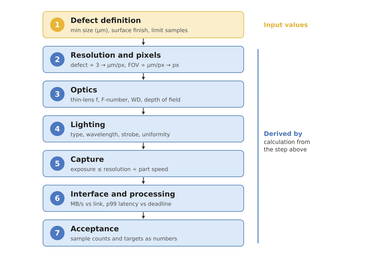
The figure links the seven lines with arrows. Put in the cover’s numbers, and 100 μm ÷ 3 = 33.3 μm/px and 100 mm ÷ 33.3 μm/px = 3,000 px, so the place for a required value gets ‘at least 3,000 px across’. Choose a 4,096 px class sensor, and at 24.4 μm/px the defect covers about 4.1 pixels, leaving a little over one pixel of margin. Lens and distance are back-calculated from the same numbers in the manner of the lens calculator article.
In the request, write something like ‘at least 3,000 px across, WD from the lens front of at least ○○ mm, smallest defect held at three pixels within a height variation of ±○ mm’. Written this way, even if a supplier proposes a different layout that splits the field between two cameras, it can be compared on the same yardstick. To compare the cameras themselves, I suggest asking for measurement data in the EMVA 12886 format (quantum efficiency, dark noise, saturation capacity, dynamic range) instead of each maker’s own notation. Write a calculated item as if it were a required value, and there is no longer any way to check whether a supplier is matching that number or matching the defect definition.
Speed sets exposure, and exposure sets the light
The lighting line states conditions more than type names: candidate methods, wavelength, continuous or strobed, the exposure time limit and uniformity. If the part is shot while moving, the distance it travels during the exposure must not exceed one pixel for it to come out without motion blur7, so the exposure time limit is pixel resolution ÷ part speed.
For the cover, that is 24.4 μm ÷ 100 mm/s = 244 μs. Assuming a reference exposure of 2 ms under continuous light, reaching the same brightness at 244 μs takes about 8.2 times the light. Only with this number in the request can the lighting supplier judge whether continuous light will hold or whether strobe overdrive8, firing the light harder than its rating for a brief moment, is needed (strobe overdrive article). The control conditions of the transport mechanism that moves the part need a separate review.
Along with uniformity, the lighting line also states what happens when light output drops over time: the interval for monitoring a reference patch placed in a corner of the frame, the recalibration interval and the like. How LED output declines gradually is calculated separately in the LED degradation article. Without this line, a setup that was right at acceptance can grow darker months later without any alarm.
Bandwidth and latency are specified down to the tail
Two of the last three lines are the data path and the processing time. If pixel count × bit depth × frame rate exceeds the bandwidth9 of the camera interface, either resolution or speed has to be cut, and processing time has to be judged by whether the tail latency crosses the deadline, more than by the average.
Receiving 4,096 × 3,000 px 8-bit images at 10 per second takes 122.9 MB/s. Assuming an effective rate of about 115 MB/s for a 1GigE link, its theoretical 125 MB/s minus the share taken by packet headers, that overflows by a little over 7%. On the same link, 9.36 frames per second is the ceiling. Holding 10 frames means moving to a wider link or sending only the region of the image that is inspected, while staying on 1GigE means cutting to 9 frames or fewer. Which way fits follows the calculation in the interface bandwidth article, and the request states the required bandwidth (MB/s) together with the link type. I never leave this line out, because a bandwidth overrun otherwise shows up only on the first day of commissioning, as dropped frames.
Processing time is specified as p99 latency10. The moment a decision signal crosses the deadline comes from the rarely stretched tail more than from the average. On a line where one part passes every second, if 1 in 1,000 is late, 28.8 parts in 8 hours do not receive a verdict within the deadline. A request that lists only the average accepts even such a system as meeting the spec. How to break it down by stage is in the p99 latency budget article.
What 299 samples can promise
Acceptance terms are the last line of the request and the easiest one to leave blank. Without them, the standard for ‘it works’ gets decided after the contract. I would write sample counts and targets as numbers: so many false detections in so many good samples, so many detections out of so many NG boundary samples. The catch is that a sample count can only promise so much.
Catching all n NG samples does not mean the miss rate is 0%. An inspector that misses with probability p catches n samples in a row with probability (1 − p)^n, and the p at which that falls to 5% is the limit chance can still explain. So with zero misses observed, the upper bound on the miss rate that can be stated with 95% confidence is 1 − 0.05^(1/n), and 3/n, known as the rule of three11, approximates it. Catch all 30 NG samples, and the upper bound is 9.5%; with 59 it is 4.95%, and with 299 it is 1.0%. To be promised a miss rate of 1% or lower, close to 300 NG boundary samples are needed. Thirty will not do.
299samples
NG samples needed to state a miss rate of 1% or less at 95% confidence (zero misses)
244μs
Exposure time limit at 24.4 μm/px and 100 mm/s
122.9MB/s
Bandwidth needed for 4,096 × 3,000 px, 8-bit, 10 frames per second
Of the three numbers, 299 is the one most easily left out of a request. To my eye, it is where any negotiation of acceptance terms starts. This calculation serves to pick a realistic promise at the quoting stage. If 300 NG samples cannot be gathered, start with a 5% miss-rate target and 59 samples, or split samples by defect type and concentrate them on the most dangerous defect. The same formula applies to false detections: zero false detections in 299 good samples supports a false detection rate of 1% or lower at the same confidence.
Bound into one spec sheet
Bound into one spec sheet, the six steps read as below. The numbers are from the injection-molded cover example, and the basis column records which line each number was calculated from.
| Item | Value | Condition · basis | In plain words |
|---|---|---|---|
| ① Minimum defect size | Dark spots and particles 100 μm in diameter, boundary samples attached | Starting value for every calculation. Surface: matte gray molding (mostly diffuse reflection) | Write the smallest defect in μm |
| ② Resolution · pixels | 33.3 μm/px or finer → at least 3,000 px across (24.4 μm/px and 4.1 px with 4,096 px) | Minimum defect ÷ 3, FOV 100 mm ÷ resolution | Pixel count is the result of a division |
| ② Lens · WD | Focal length back-calculated with the thin lens equation, WD in mm from the lens front including light and fixture space | Checked against the installation drawing; height variation ± mm as the depth-of-field requirement | The distance between lens and part is promised on a drawing |
| ② Exposure · lighting | Exposure limit 244 μs (100 mm/s assumed), candidate methods, wavelength, uniformity, degradation handling | Pixel resolution ÷ part speed. 8.2 times the light of a 2 ms reference exposure | No more than one pixel of smear while moving |
| ③ Algorithm · processing | Required bandwidth 122.9 MB/s (10 fps), p99 latency ≤ decision deadline | Compared with an assumed 1GigE effective rate of about 115 MB/s. Never the average alone | Look at the link and the deadline down to the tail |
| ③ Acceptance | All 299 NG boundary samples detected (miss rate ≤ 1%, 95% confidence), zero false detections in 299 good parts | Upper bound with zero observed = 1 − 0.05^(1/n) ≈ 3/n | The sample count sets what can be promised |
Read the table from top to bottom, and the first thing that shows is that each line is the calculated result of the line above. Suppliers who receive a request filled in this order part ways only on design choices, not on how they read the conditions, and only then can the quotes be set side by side and compared. Start instead from the pixel count in ②, and the link to ① breaks, bringing proposals in which the same pixel count covers the defect with a different number of pixels each time. I suggest attaching this table in front of the body of the request.
Sometimes this order is more than needed. For a new process whose defect definition itself is not settled, contracting a sample evaluation stage first beats an equipment request. When a proven setup is brought in again as it is, reusing the existing spec sheet and managing only changes in material and lot is faster. For a simple presence check that only asks whether a part is there, three lines (FOV, WD and processing time) may be enough instead of all seven steps.
The calculation that runs from defect size to the number of acceptance samples trains the eye of anyone starting out as an equipment engineer for reading spec sheets. From the side that compares quotes and sets the budget, one well-built request narrows the gap between quotes more than haggling over camera prices does. This article explains technology and is not investment advice. See our Disclaimer.
Field Note
Before a request goes out to suppliers, I would first line up the defect definition table and the acceptance line. Without defect size, material and reflectance written as numbers, each supplier sets the FOV and lighting differently and the proposals cannot be compared. The WD from the lens front and the installation drawing are attached to that table, and the acceptance cell holds both the number of NG samples that can be secured and the miss-rate upper bound that number can support. With only 30 samples, the figure in that cell is 9.5%.
Field Checkpoints
Before moving the field note’s table into the request, answer the questions below.
- Are the WD from the lens front and the light and fixture space written as numbers in the request, with a drawing? (so suppliers do not each assume a different distance)
- Are the minimum defect (μm) and surface material defined in numbers and terms, with boundary samples attached? (if the first line is empty, so is the rest)
- Are pixel count and focal length written as values derived from resolution? (100 μm ÷ 3 → 33.3 μm/px → 3,000 px)
- Is the exposure time limit, calculated from resolution and part speed, part of the lighting conditions? (24.4 μm ÷ 100 mm/s = 244 μs)
- Are the required bandwidth and the processing time requested as p99 instead of an average? (122.9 MB/s exceeds the 1GigE effective rate)
- Does the sample count in the acceptance terms match the miss rate to be promised? (about 300 NG samples for 1% or less; 30 samples support 9.5%)
Frequently Asked Questions
Should the camera pixel count be left out of the request entirely?
Write it, but with its basis. Leave the derivation, as in ‘minimum defect 100 μm, FOV 100 mm → resolution 33.3 μm/px or finer → at least 3,000 px across’, and even a proposal that splits the field between two cameras can be compared on the same standard.
Why is processing time written as p99?
Because the moment a decision signal crosses the deadline comes from the rarely stretched tail. With only the average written down, even a system that is late on roughly 1 in 1,000 parts meets the spec. The request should state the measurement conditions (number of parts, continuous running time) along with p99 so the figure can be measured again.
How are acceptance terms written with only a few NG samples?
Write down exactly the upper bound that the secured sample count can support. Catch all 20 NG samples, and the miss-rate upper bound that can be stated with 95% confidence is about 13.9%. If that number is uncomfortable, gather more samples, or concentrate them on the most dangerous defect type to lower the bound at least for that defect.
Glossary
- [1] Request for quotation RFQ
A document that sets out the conditions of the equipment to be bought and asks several suppliers for quotes. Only conditions written as numbers make the returned quotes comparable. ↩ - [2] Boundary sample limit sample
A real part that sits on the boundary between pass and fail. It leaves less room for interpretation than a criterion written in words. ↩ - [3] Pixel resolution μm/px
The length on the inspected surface that one pixel covers. At 24.4 μm/px, each pixel is responsible for 24.4 μm of the part. ↩ - [4] WD working distance
The distance from the front of the lens to the surface being inspected. Lights and fixtures have to fit in this gap, so it is promised on a drawing. ↩ - [5] Depth of field DOF
The range of depth that stays sharp in front of and behind the focus distance. Part height variation has to fit inside it. ↩ - [6] EMVA 1288 camera measurement standard
A standard that sets one method for measuring and reporting the performance of machine vision cameras and image sensors. Numbers from different makers can then sit side by side. ↩ - [7] Motion blur motion blur
Smearing of the image because the part moves during the exposure. It is the streak a moving car leaves in a photo taken with a slow shutter. ↩ - [8] Strobe overdrive strobe overdrive
A drive method that pushes more than the rated current through an LED for a short pulse to raise its momentary brightness. It switches off before heat builds up because the on-time is short. ↩ - [9] Bandwidth MB/s
The amount of data the link between camera and computer can carry in one second. Image size times frame count has to stay below it. ↩ - [10] p99 latency 99th percentile
The value at the 99th percent mark when latencies are lined up from shortest to longest. It exposes the tail that runs late one time in 100 even when the average looks fine. ↩ - [11] Rule of three rule of three
An approximation that puts the rate of an event never seen in n trials at 3/n or below with 95% confidence. The exact value is 1 − 0.05^(1/n). ↩
References
- EMVA 1288, Standard for Measurement and Presentation of Specifications for Machine Vision Sensors and Cameras (Release 4.0)
- Rule of three (statistics), Wikipedia: with zero events in n trials, 0 to 3/n is a 95% confidence interval
- Formulas: pixel resolution = minimum defect ÷ 3, required pixels = FOV ÷ resolution, exposure limit = pixel resolution ÷ part speed, bandwidth = width × height × bytes per pixel × frame rate, 95% upper bound with zero observed = 1 − 0.05^(1/n). Assumptions: 1GigE effective 115 MB/s, reference exposure 2 ms, one part per second
Related reading — How to Calculate Machine-Vision Lens Focal Length · Six Machine-Vision Lighting Methods and How to Choose · In the Age of Deep-Learning Inspection, What to Check Before Camera Spec

Noctvision
An engineer who has handled mechanical design and project management for production equipment since 2005. Here I work through the cameras, lenses and lighting that go into equipment with formulas and public data, and record the assumptions and sources alongside the numbers.


You May Also Like
How Strongly Cross-Polarization Suppresses Glare Depends on the Lighting Angle
A Depth Camera’s Error Grows with the Square of Distance