The Black Spot in the Middle of a Dome Light Is the Camera Hole
LIGHTING
The black dot in the middle of a dome light is the camera hole reflected in the part, and in this setup it covers 0.53 mm, 81 pixels across.
With a plated cap of 6 mm radius of curvature and a dome 180 mm across, I calculated the size of the dark spot, the trade between dome size and WD, and the ring beyond 45° that no dome can fill.
About 12 min read
Put a chrome-plated convex metal cap under a ring light and the image breaks into pieces. A plated surface is a mirror-like surface with high reflectance, so only the directions the light comes from blow out white and the rest sinks to black, leaving more than half the surface uninspectable. Move to a dome light and the bands disappear, but one black dot remains in the middle of the evenly lit image.
Read the dot as a defect and every part fails. Cover it with a mask, and the plating pinholes and dents that fall inside are never inspected again. On a convex part this dot lands, of all places, at the front center, the spot a customer sees first, so the area left under the mask becomes the area that matters most.
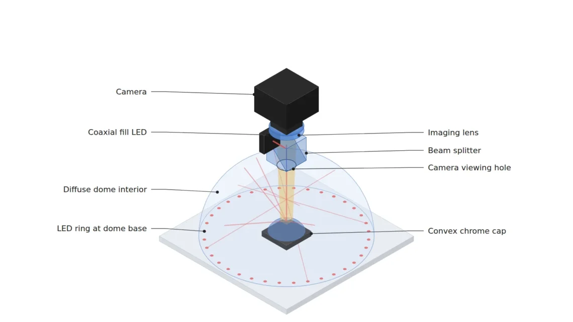
The black dot is neither a defect nor a lighting fault; it is the image of the viewing hole at the top of the dome, reflected in a curved mirror. Since the cause is geometry, the size comes out of a calculation too. I fixed a cap with a 6 mm radius of curvature and a dome 180 mm across, then calculated in turn the diameter of the dark spot, the WD that gets pushed out as the dome grows, and the conditions for a coaxial fill light that puts light back toward the hole.
Like an overcast sky, a dome fills every direction
A mirror-like surface returns light by specular reflection1, so what the camera sees is less the surface itself than the scene in the direction its surface normal2 points to. A point whose normal tilts by φ reflects the direction 2φ away from the optical axis, and on a convex surface this tilt spreads continuously from 0°. When light comes from only a few directions, as with a ring light, only the bands reflecting those directions are bright and the rest is dark. A dome light3 makes the whole diffusing surface inside the hemisphere glow at nearly the same brightness, so whichever direction a point reflects, a similar brightness comes back.
It is like an overcast day with low clouds, when a person standing in a schoolyard casts almost no shadow. The whole sky is evenly bright, so it is hard to tell where the light comes from. Image a plated connector shell that mixes a cylindrical face with rounded corners under a ring light and bright and dark bands alternate, burying a 30 μm dent at a band edge; put it inside a dome and the whole surface settles into a similar grey, so the dent rises as a small spot whose tilt differs from its surroundings.
When designing a dome, the goal I set is to fill every direction the part can reflect with the same brightness, more than to make it bright. There are two directions where that goal breaks. One is the hole at the top through which the camera looks down, and the other is any direction lower than the bottom edge of the dome. Plating thickness and gloss change the reflection of this material widely, so how well this calculation matches real images cannot be guaranteed before a sample test.
The reflected camera hole is 0.53 mm across
The viewing hole gives no light. It is only a hole cut in the top of the dome. With hole diameter d and dome inner radius Rd, the half-angle of the hole seen from the part is γ = atan(d/2 ÷ Rd). A point with normal tilt φ reflects the direction 2φ, so wherever 2φ is smaller than γ, the point reflects the hole and images dark. On a convex surface with radius of curvature R, the radius of that area is R × sin(γ/2).
Assume a cap with a 6 mm radius of curvature imaged through a dome 180 mm across with a ø16 mm viewing hole: γ is 5.08°, the dark spot radius is 6 × sin 2.54° = 0.27 mm, and its diameter 0.53 mm. With a 2,448 × 2,048 px sensor and a 50 mm F/8 lens viewing 16.0 mm across, one pixel covers 6.54 μm, so the dark spot becomes a black circle 81 px across, big enough to cover dozens of 25 μm pinholes (3.8 px). Shrink the dome to 120 mm across and γ grows to 7.59°, enlarging the spot to 0.80 mm, 122 px.
0.53mm
Central dark spot with a 180 mm dome and a ø16 mm hole
0.39mm
Dark spot left even with the hole cut to the 11.8 mm imaging beam
72%
Inspectable area of the cap after the ring beyond 45° is removed
Shrinking the hole further seems like the fix, but there is a limit. The hole has to be large enough not to clip the imaging beam4 entering the lens, and for this setup the beam, calculated from the field diagonal and the entrance pupil, is 11.8 mm across at the height of the hole. Even with the hole cut to exactly that size, a dark spot 0.39 mm, 60 px across remains. I would put the effort into making light come from the direction of the hole as well, more than into shrinking the hole.
Grow the dome and the lens moves farther away
The diameter of the dark spot shrinks roughly in inverse proportion to the dome radius. A dome 240 mm across brings the spot down to 0.40 mm with the same hole. Yet the camera has to sit above the top of the dome, and putting a coaxial fill light on top adds the height of the half mirror5 module. Assuming a module height of 40 mm, a 180 mm dome needs a WD of 130 mm and a 240 mm dome needs 160 mm. The thin-lens object distance of the current lens is 144.7 mm, so a 240 mm dome leaves no room with this lens.
A plausible idea
Grow the dome and shrink the hole, and the dark spot goes away.
Run the numbers
Cut the hole to 11.8 mm and 0.39 mm still remains; a 240 mm dome needs a 160 mm WD.
The two numbers on the right of the card mark the end of what dome size can solve. Masking the dark spot has a trap too. The spot forms where the normal is nearly parallel to the optical axis, so when the part tilts, that place moves with it. Tilt the cap by 1° and the center of the spot shifts by 6 × sin 1° = 0.105 mm, 16 px, and by 32 px at 2°. Covering it with a fixed mask means enlarging the mask by the tilt range, so the uninspected area grows larger than the spot itself.
There are attempts to hide the hole in other ways. US patent US9467609B2 from Mettler Toledo LLC points out that the dark spot formed by the reflected central opening of a dome can make a code printed on the surface unreadable, and notes that a cloudy day illuminator using a beamsplitter is expensive and bulky, with a beamsplitter that is fragile and hard to clean. As an alternative it places a diffusely reflecting cover with very narrow slits or holes over the opening, close to the lens and out of focus, so the reflected opening blends into the surrounding illumination. The patent itself describes the result as adequate for typical OCR, so for plating appearance where 25 μm pinholes must be caught, I would look at a coaxial fill light first.
Coaxial fill light covers the hole, not beyond 45°
Place a half mirror above the viewing hole and send light down along the optical axis, and light reaches the places where the part used to reflect the hole, so the dark spot disappears. This is the structure of cloudy day illumination6. The key is matching the brightness of the fill light to the inside of the dome. If the fill light is darker than the dome a faint dark spot remains, and if it is brighter a bright circle remains instead, inviting over-detection either way. The coaxial path passes the half mirror twice and returns at most 25% of the source output, so the fill light goes on an independent channel whose brightness is adjusted apart from the dome.
There is one more dark zone. Even the fill light cannot reach it. A point whose normal tilts beyond 45° has 2φ past 90°, so it reflects a direction below the horizontal. If the bottom edge of the dome sits at the height of the part, there is no glowing surface in that direction. The cross-section below draws the hole spot in the middle and the 45° dark zone at the rim in one picture.
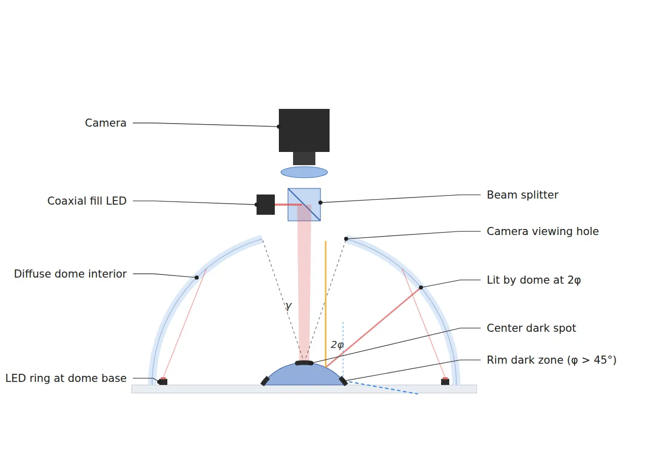
On a cap with a 6 mm radius of curvature and 10 mm diameter, the radius where the normal reaches 45° is 6 × sin 45° = 4.24 mm. From 4.24 mm out to 5.0 mm, a ring 0.76 mm (116 px) wide stays dark however the fill light is tuned. By area, only 72% of the cap can be inspected. No signal reaches that place, so there is no way to brighten it with image processing and inspect it either. This ring is split off the judgment area (ROI)7 and handed to a low-angle lighting station, or a design that lowers the bottom edge of the dome below the part to put light below the horizontal is reviewed separately.
From a 25 μm pinhole to a 130 mm WD on one sheet
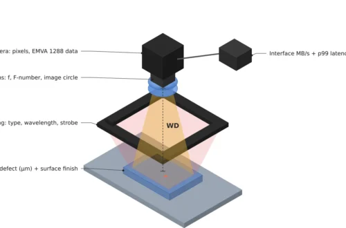
Once the borders of the two dark zones are known, the numbers for the spec fall into place. The WD (working distance)8, the distance from the front of the lens to the part, has to hold both the dome radius and the height of the half mirror module, and the algorithm starts from a polar unwrap9 that flattens the concentric brightness around the center of the cap.
| Item | Reference value | Condition and basis | In plain words |
|---|---|---|---|
| ① Minimum defect size · pinhole | 25 μm across or more | 3.8 px at 6.54 μm/px. Design assumption | A dot about four pixels wide |
| ① Minimum defect size · dents and stains | Dents 30 μm wide or more, plating stains 100 μm across or more | Dent 4.6 px, stain 15.3 px (low contrast). Design assumption | Stains are large but faint, so they get their own check |
| ② Optical setup · lighting | Diffuse dome 180 mm across, ø16 mm viewing hole, coaxial fill light on its own channel | Hole larger than the 11.8 mm imaging beam at that height. Dark spot 0.53 mm without the fill light | Light also comes from the hole direction |
| ② Optical setup · dark-zone borders | Central spot 0.53 mm across, outer dark zone beyond a 4.24 mm radius | R × sin(γ/2), R × sin 45°. Cap radius of curvature 6 mm assumed | There are blind spots in the middle and at the rim |
| ② Optical setup · lens and sensor | 50 mm F/8, 2,448 × 2,048 px, 6.54 μm/px | Magnification 0.528, thin-lens object distance 144.7 mm. Design assumption | 16 mm across in one image |
| ② Optical setup · WD | WD of 130 mm or more secured | Dome inner radius 90 mm + half mirror module 40 mm (assumed). Confirm with the lens spec and a measurement | The dome and fill light have to fit under the lens |
| ③ Algorithm parameters · coordinates | Polar unwrap around the cap center | Turns the concentric brightness into a background that is even along rows | Straighten round brightness into lines |
| ③ Algorithm parameters · judgment | Mean and standard deviation template from 30 good parts, deviation over 4σ with area 9 px or more | Re-acquire after matching the fill light. 4σ and 9 px are assumptions | Keep only spots outside the normal range |
| ③ Algorithm parameters · region | Ring beyond a 4.24 mm radius excluded, sent to a separate station | No signal reaches it, so it is not something to correct | Inspect the blind area elsewhere |
The first thing the table shows is that the inspectable area of this setup is bound by the dark-zone borders more than by resolution. A 25 μm pinhole at 6.54 μm/px is 3.8 px, past my rule of 3 px, but without the fill light the central 81 px are covered, and even with it the 116 px ring at the rim does not come back. So I write the detection spec of a cap like this as the pinhole size together with an inspectable area of 72%.
There are parts a dome clearly does not suit. On flat mirror-like parts the normals bunch tightly, so most of the wide glowing surface of the dome goes unused and only adds stray light, and a small coaxial light with higher contrast does better. On parts with relief or engraving to read, a dome erases the edge contrast that height differences create, so low-angle lighting wins. In a cramped place where WD is hard to secure, shrinking the dome enlarges the dark spot and growing it pushes the lens away, so lighting several directions in turn and combining the images is the option to review. The gloss and fine texture of chrome plating vary with plating conditions, so whether a dome or another method does better also cannot be guaranteed before a sample test.
Calculating a dark spot from the radius of curvature and the hole size is one of the first geometry exercises a vision engineer who designs lighting learns, and it takes two lines, an atan and a sin. On the side buying the equipment, asking what percentage of the part remains inspectable once the dark spot and the 45° ring are taken out tells more precisely about real detection range than a line that reads dome lighting applied. This article explains technology and is not investment advice. See our Disclaimer.
Field Note
To look at a plated cap under a dome light, I would calculate the diameter of the central dark spot and the radius of the 45° border from the radius of curvature on the drawing before choosing the dome. In this setup they are 0.53 mm and 4.24 mm, and while a coaxial fill light can cover the hole spot, the outer ring does not come back with any adjustment. Next comes measuring how far the cap tilts on the jig to see how many pixels the spot moves, and tuning the fill light separately until its grey matches the dome. When a model with a different curvature comes in, both borders get calculated again.
Field Checkpoints
Once the two borders and the jig tilt have been checked by calculation, I answer the questions below one at a time.
- Is a WD of 130 mm or more secured by measurement, including the dome inner radius and the half mirror module height? (whether the dome and fill light fit under the lens)
- Have the surface material and reflectance of the part been confirmed first? (chrome plating, nickel plating, or a matte finish)
- Is the viewing hole wide enough not to clip the imaging beam? (11.8 mm or more in this setup)
- Have the central dark spot diameter and the 45° border radius been calculated from the radius of curvature of the part? (how much is blind in the middle and at the rim)
- Has it been checked how many pixels the spot moves with jig tilt? (16 px per 1°)
- Is the coaxial fill light on its own channel with its grey matched to the inside of the dome? (whether the middle shows dark or bright)
- Does the pixel resolution give the smallest pinhole 3 px or more? (25 μm is the floor at 6.54 μm/px)
Glossary
- [1] Specular reflection specular reflection
Reflection from a smooth surface that bounces light off in one direction only, at the same angle it arrived. It is why a plated surface mirrors its surroundings. ↩ - [2] Surface normal surface normal
The direction standing perpendicular to the surface at a point. On a convex cap the normal leans further from the center toward the rim. ↩ - [3] Dome light dome light
Lighting that makes the whole inside of a hemisphere glow evenly and gives light from every side. A hole at its top lets the camera look down. ↩ - [4] Imaging beam imaging beam
The bundle of light that starts from each point of the part and enters the lens opening. Blocking where it passes darkens the edges of the image. ↩ - [5] Half mirror beamsplitter
A mirror that reflects half the light and passes half. It sends the fill light down onto the optical axis while letting the line of sight of the camera pass through. ↩ - [6] Cloudy day illumination cloudy day illumination
A lighting setup that adds a half mirror and a fill light above a dome so light also comes from the direction of the camera hole. The name comes from the shadowless sky of an overcast day. ↩ - [7] ROI region of interest
The region of the image where judgments are made. Places that receive no signal are cut out of it. ↩ - [8] WD working distance
The distance from the front of the lens to the surface being inspected. With a dome light, the dome radius and the height of any module on top have to fit within it. ↩ - [9] Polar unwrap polar unwrap
A transform that unrolls an image around a circle center into radius and angle axes. Concentric brightness changes turn into stripes running one way. ↩
References
- Mettler Toledo LLC, US patent US9467609B2, Machine vision inspection systems and methods and aperture covers for use therewith (priority and filing May 10, 2013; granted October 11, 2016. The dark spot from the reflected central opening of a dome and the code-reading problem, drawbacks of cloudy day illuminators, and a narrow-slit cover that blends the opening into the surrounding illumination)
- Formulas: hole half-angle γ = atan(d/2 ÷ Rd), dark spot radius = R × sin(γ/2), 45° border radius = R × sin 45°, imaging beam diameter at the hole = 2 × (H × (1 − Rd/u) + P × Rd/u) (H half field diagonal, P entrance pupil radius, u object distance), spot shift with part tilt = R × sin δ, pixel resolution = field of view ÷ pixel count, u = f × (1 + 1/m), half mirror round trip = 0.5 × 0.5
Related reading — For Scratches on Highly Reflective Metal, Choose the Lighting First · Coaxial Light Alone Does Not Settle Fine Scratches on Polished Metal · Raising the Camera Leaves the Glint of Its Built-in Light in Place

Noctvision
An engineer who has handled mechanical design and project management for production equipment since 2005. Here I work through the cameras, lenses and lighting that go into equipment with formulas and public data, and record the assumptions and sources alongside the numbers.


You May Also Like
How to Handle Imaging on Highly Reflective Surfaces
What to Write First in a Spec Sheet Before Buying Machine Vision Equipment